In previous posts we’ve explained the use case of virtual wire interfaces and configured a basic virtual wire deployment and with VLAN subinterfaces. NAT might be needed and it isn’t an easy task with virtual wire interfaces because additional routes are required to make the router aware of the NAT address pool.
Source NAT
The example below will illustrate the idea of doing source NAT with Virtual Wires.
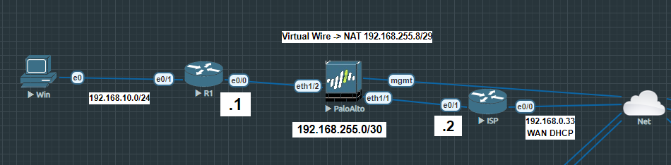
The ISP router is directly connected with my local network so that it provides internet access. R1 is the router where clients are connected to. The PA firewall is deployed in-between because it has to translate anything coming from R1 before it hits the ISP router. The ISP router translates everything it receives from the inside interface to 192.168.0.33, so it can communicate with my home network (192.168.0.0/24). The NAT address pool on the PA is 192.168.255.8/29. The subnet between R1 and ISP is 192.168.255.0/30. It’s important that the subnet between the routers and the NAT address pool on the PA are different.
For R1 we have to add a default route pointing to the inside interface of the ISP router.
R1(config)#ip route 0.0.0.0 0.0.0.0 192.168.255.2
R1(config)#int e0/0

R1(config-if)#ip address 192.168.255.1 255.255.255.252
R1(config-if)#no sh
R1(config)#int e0/1
R1(config-if)#ip address 192.168.10.1 255.255.255.0
R1(config-if)#no sh
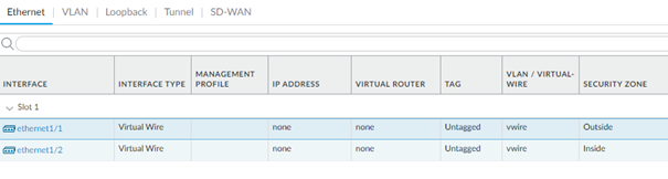
Moving on the PA firewall, we’ll configure ethernet1/1 as the outside interface and ethernet1/2 as the inside interface.
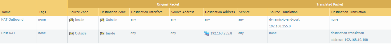
Add a NAT policy and select Inside as the source zone and Outside as the destination zone. Translate the source to 192.168.255.8/29 and leave the destination empty because we’re doing a source NAT.

Next we’ll configure our ISP router. The first route is the default-route and the second route we’ve added is quite tricky to understand. Basically if the NAT address pool is 192.168.255.8/29, you have to add a route to that subnet so that the ISP router doesn’t drop that packet. The next-hop should be the external interface of R1.
ISP(config)#ip route 0.0.0.0 0.0.0.0 192.168.0.1
ISP(config)#ip route 192.168.255.8 255.255.255.248 192.168.255.1
ISP(config)#int e0/0
ISP(config-if)#ip address dhcp
ISP(config-if)#ip nat outside
ISP(config-if)#no sh
ISP(config)#int e0/1
ISP(config-if)#ip address 192.168.255.2 255.255.255.252
ISP(config-if)#ip nat inside
ISP(config-if)#no sh
ISP(config)#access-list 1 permit 192.168.255.0 0.0.0.3
ISP(config)#access-list 2 permit 192.168.255.8 0.0.0.7
ISP(config)#ip nat inside source list 1 interface e0/0 overload
ISP(config)#ip nat inside source list 2 interface e0/0 overload
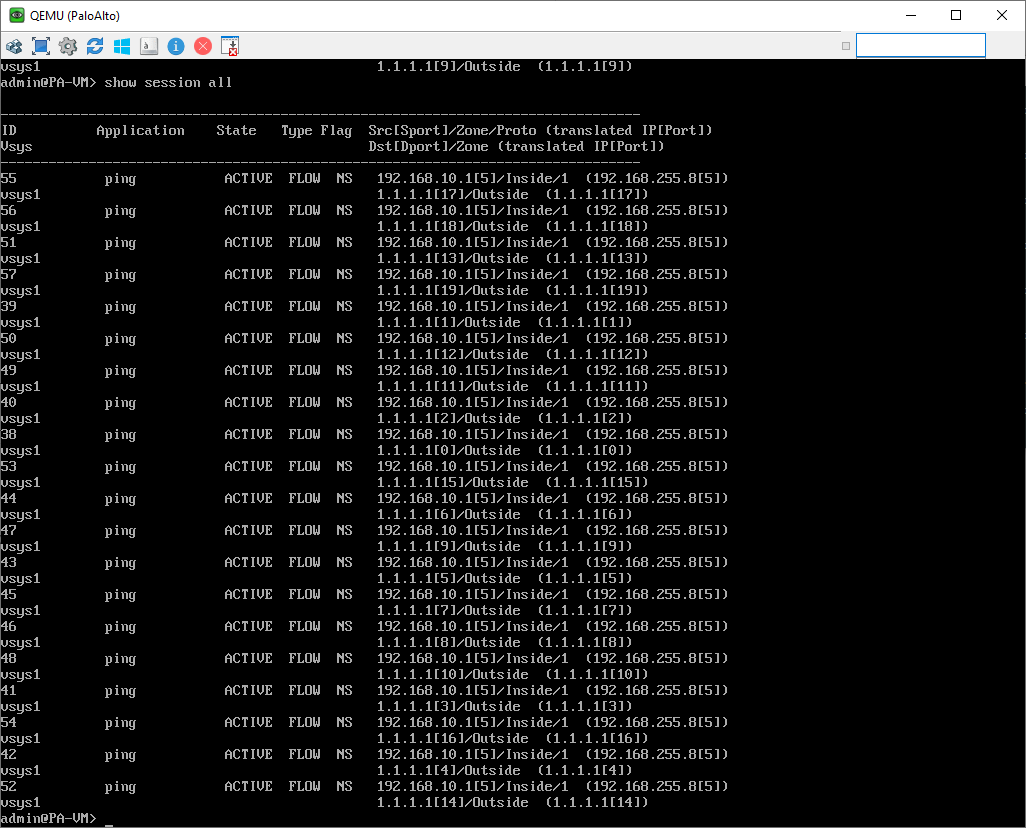
Let’s ping from the inside interface of R1 to 1.1.1.1
R1(config)#do ping 1.1.1.1 source 192.168.10.1 repeat 20And on the PA issue the command ‘show session all’ to see if anything coming from 192.168.10.0/24 is translated to 192.168.255.8/29 (the NAT pool on the PA).
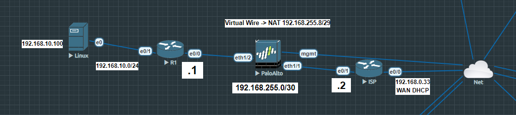
Destination NAT
Destination NAT is required to make a webserver publicly available. I’ve replaced the Windows 10 client with a Linux server running Apache2. Then I’ve assigned it with the IP address of 192.168.10.100/24.
On the PA firewall add a destination NAT from the ‘Outside’ zone to the ‘Inside’ zone. You can define the services/ports if you wish. You might have to remove the subnetmask in the source NAT policy.
Next, on the ISP router we need to port forward TCP/80 traffic to the NAT address of the PA. Basically, 192.168.0.33:80 -> 192.168.255.8:80
ISP(config)#ip nat inside source static tcp 192.168.255.8 80 192.168.0.33 80Browsing to http://192.168.0.33 will be forwarded to 192.168.255.8/29 and then the PA will translate it to the webserver’s private IP address 192.168.10.100/24 as defined by the NAT policy.