In a previous post, we’ve configured a basic Virtual Wire deployment but you should realize that you’ll eventually run out of physical interfaces to add new networks. If the parent interface was configured as an access (untagged) VLAN – that means that you’ll have to use another physical interface to add a 2nd untagged VLAN and so on.
Router-on-a-stick is a very popular setup used in a lot of scenario’s within many enterprises. The benefit to this method is that we do not need to use other physical interfaces or add another cable. Instead we can create sub-interfaces under a parent interface if we want to add a new VLAN/network. It’s absolutely mandatory to carry the same methodology over to virtual wires in a router-on-a-stick setup.
Prerequisites
- See my previous post to deploy basic virtual wire interfaces
- Understanding of VLAN basics such as Access/untagged & Trunk/tagged ports
- Able to configure vSwitches in ESXI or dSwitches in vCenter
- Edge router/internet gateway
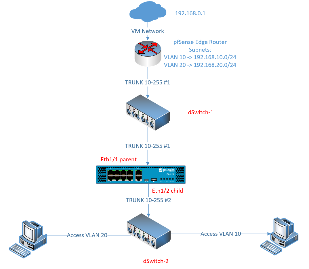
Lab Setup
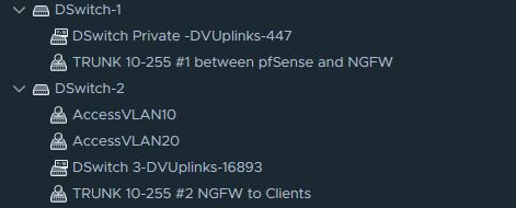
Preparing the switches
We’ll need two switches which I’ll refer to as dSwitch-1 and dSwitch-2. Each of them needs to have their own TRUNK-link Portgroup with a range of your choice. Access ports which clients and servers will use, are configured on dSwitch-2. If we don’t separate L2, clients/servers with access ports will communicate directly with the Edge Router instead and that’s not the intended objective here.
If you’re using VM Network as an up-link to your virtual machines then you do not need to configure an up-link on the dSwitches. I’ve used VM Network just for the Edge router (pfSense in my case).
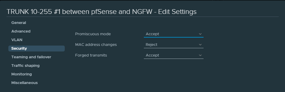
Also enable the following security settings for the first and second trunk link portgroups.
Preparing the VM interfaces
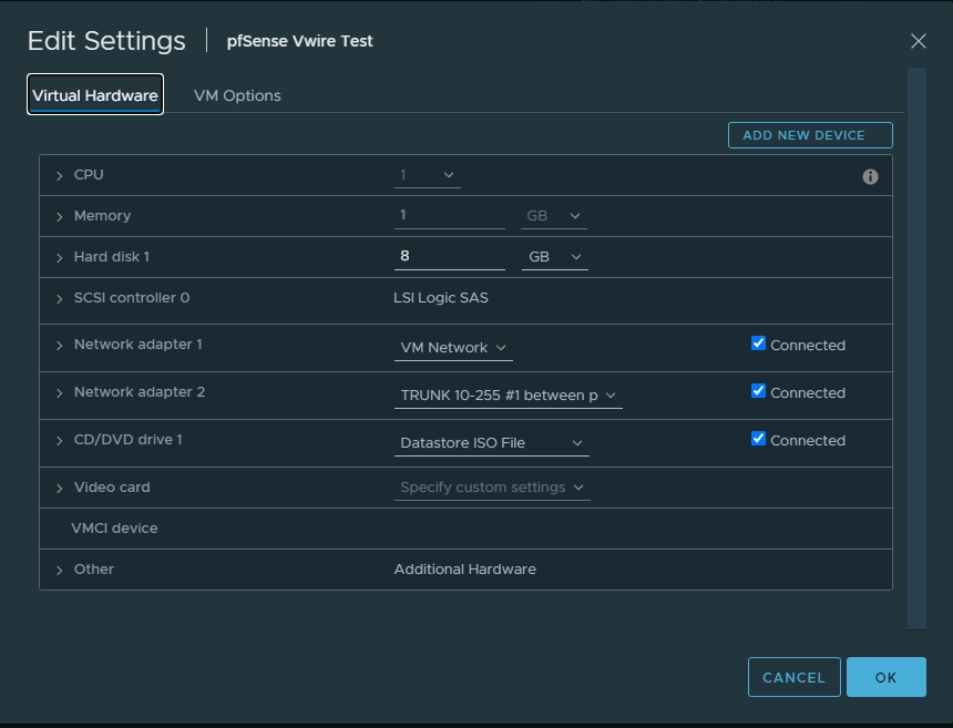
For the Edge Router we’ll use the TRUNK interface of dSwitch-1
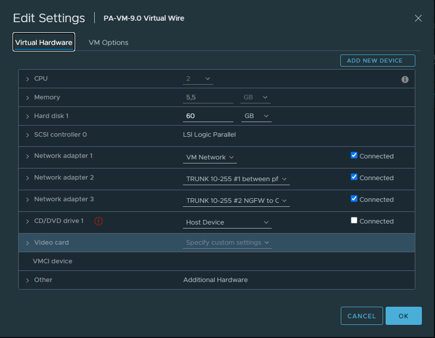
On the Palo Alto we’ll use the same TRUNK interface of dSwitch-1 as the parent interface, or in other words the wire that connects with the Edge Router (pfSense).
We’ll use the TRUNK interface of dSwitch-2 as the child interface to provide connectivity to clients. (VM Network here is just used for the Management Interface because that’s how it suits me).
Spin up a client and configre it with an access portgroup of VLAN 10.
Virtual Wire configuration
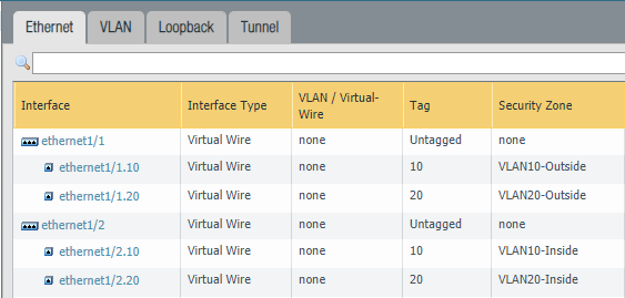
Change the type to a Virtual Wire interface for the parent interfaces “Ethernet1/1” and “Ethernet1/2”. Do not assign the parent interfaces any zones because it’s unnecessary.
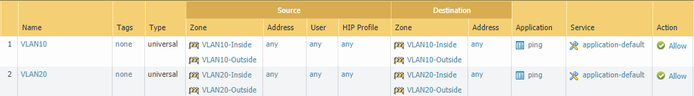
Then add sub-interfaces for VLAN 10 and VLAN 20. Make sure to use two different security zones. For example, “VLAN10-Inside” on the first interface and “VLAN10-Outside” on the second interface.
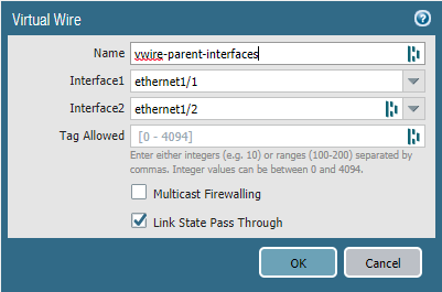
Next, we need to add a virtual-wire object to the parent interfaces “Ethernet 1/1” and “Ethernet1/2”. Leave the “Tag Allowed” field blank because we’re tagging on the sub-interfaces instead. This field is only used for when you don’t use sub-interfaces.
The benefits of using sub-interfaces is that you can assign each sub-interface its own security zone which in turn yields better visibility, segmentation, policy control and so on.
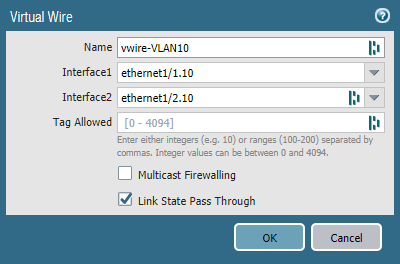
Add a vwire-object for VLAN 10. Select “Ethernet1/1.10” as the first interface and “Ethernet1/2.10” as the second interface. Leave the “Tag Allowed” field empty.
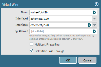
Repeat the same process but for VLAN 20.
Don’t forget to add a security policy to allow traffic to pass. NAT should be performed on the Edge router, so we don’t have create a NAT policy.