Inter-VLAN routing is simply routing traffic between one or more broadcast domains. Without the addition of a router, there’s no way to get traffic from VLAN 10 to VLAN 20 because they’re in different broadcast domains. It doesn’t necessarily require a router though. Layer-3 switches with routing properties and an SVI (Switch Virtual Interface) per VLAN ID – can do Inter-VLAN routing as well. Assuming that the SVI is configured with a logical address.
This picture illustrates it perfectly and all credits to whoever made it. We can see that VLAN 10, 20 and 30 are segmented and with the help of the routers, packets can travel through the VLAN domains. We won’t be using more than one router for this guide because that’d complicate things even more.
Assumptions
- Understanding basic concepts of VLANs and routing
- Switch with routing and VLAN support
- Palo Alto Firewall
- Non sub-interfaces are untagged e.g. the parent interface
- Sub-interfaces are tagged/trunk
- Lab environment like Eve-NG with the necessary images
Method 1: Router-on-a-stick
This is by far the most popular topology and it’s also my favorite because it’s simple to deploy with minimal configurations on the switch and almost an endless amount of interfaces to work with.
The basic idea is that the link between the firewall/router and the switch is configured as a trunk. The trunk link allows us to add new interfaces on the fly without doing any cabling. Firewalls don’t have an endless amount of ports available, so configuring them as a trunk port is essential.
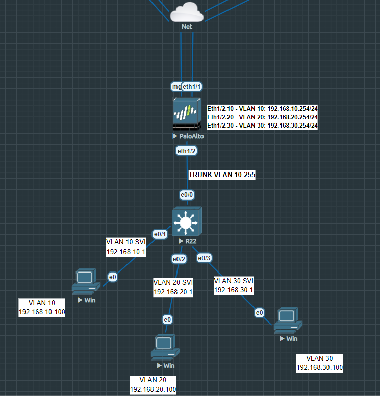
Router-on-a-stick illustrated below:
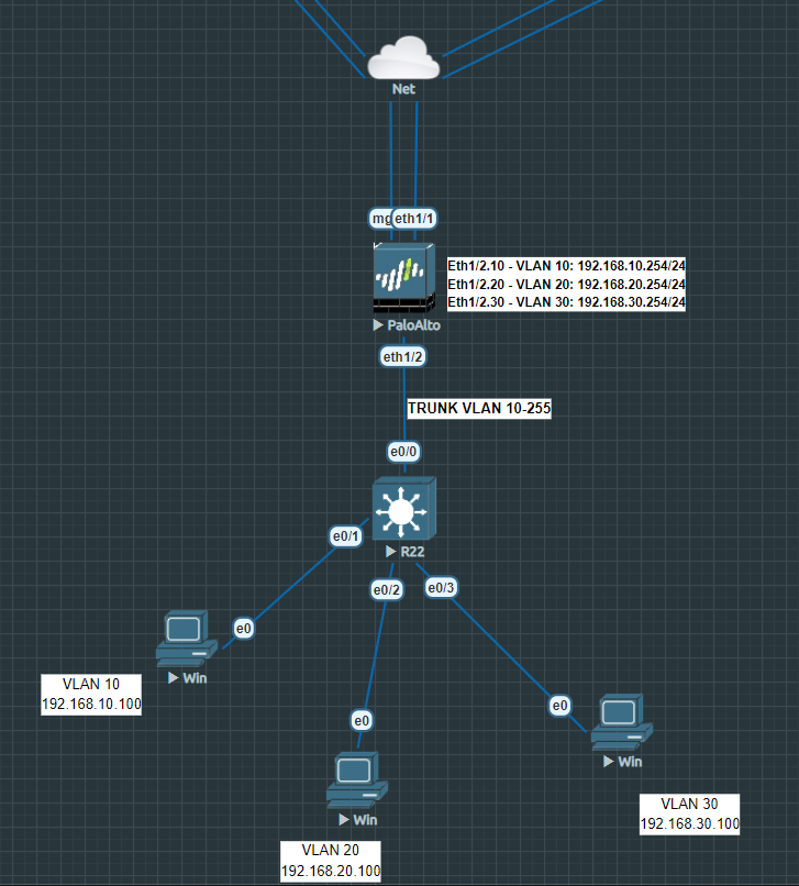
The parent interface Ethernet 1/2 should be configured as a Layer 3 interface and nothing more. So no IP-addresses or security zones attached to the parent interface. The sub-interfaces, like Eth1/2.10 and Eth1/2.20 and Eth1/2.30 will have their own security zone and subnet.
Configure the interface that you intend to use on the switch as a trunk port. The range is totally up to your preference but I recommend changing the native VLAN to a value that’s outside the trunk range. On Cisco switches it isn’t possible to turn off the native VLAN on a trunk port. So for the native VLAN, specify some random VLAN ID that you don’t plan on using.
Switch(config)#int e0/0
Switch(config-if)#switchport trunk encapsulation dot1q
Switch(config-if)#switchport mode trunk
Switch(config-if)#switchport trunk allowed vlan 10-255
Switch(config-if)#switchport trunk native vlan 3000
Switch(config-if)#no shutdown
Configure a physical interface as an Access port with VLAN 10 as ID. Repeat the same process for VLAN 20 and VLAN 30.
Switch(config)#int e0/1
Switch(config-if)#sw mode access
Switch(config-if)#sw access vlan 10
Switch(config-if)#no shutdown
Method 2: Inter-VLAN routing with a switch (SVI)
In this scenario the switch is taking care of routing traffic between the VLAN zones. It requires a Layer 3 Switch and an SVI (Switch Virtual Interface) configured in order to route. The primary benefit to this topology is that it massively reduces the load on the firewall because Inter-VLAN traffic isn’t traversing the firewall. But the drawback is that you lose policy control (like firewall rules) because that traffic is not hitting the firewall.
There’s no need for a trunk port because there’s only a single switch here. But if we add one more switch into the mix then the switches should be connected with a trunk link.
The uplink of the switch to the firewall is configured as a layer 3 interface. 192.168.1.1/24 on the Switch and 192.168.1.254/24 on the firewall.
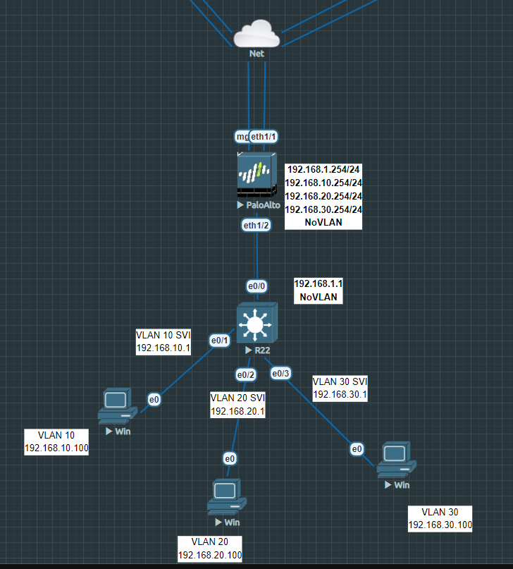
Configure the uplink port with an IP-address that’s within the same range as the firewall’s eth1/2 port.
Switch(config)#int e0/0
Switch(config-if)#no switchport
Switch(config-if)#ip address 192.168.1.1 255.255.255.0
Switch(config-if)#no shutdown
Configure a physical interface as VLAN 10 access. Do the same for VLAN 20 and VLAN 30.
Switch(config)#int e0/1
Switch(config-if)#switchport mode access
Switch(config-if)#switchport access vlan 10
Switch(config-if)#no shutdown
To configure an SVI we have to enter the VLAN interface and not the physical one. Enter the ip address and make sure to add the “no shutdown” command. Do the same for VLAN 20 and VLAN 30.
Switch(config)#int vlan 10
Switch(config-if)#ip address 192.168.10.1 255.255.255.0
Switch(config-if)#no shutdown
We’ll need a default route pointing to the firewall so that our clients have internet access. The switch’s outside interface is configured with 192.168.1.1/24 and the end on the firewall is 192.168.1.254/24.
Switch(config)#ip route 0.0.0.0 0.0.0.0 192.168.1.254Finally, it’s very important that you configure the firewall’s interface with an IP-address that’s within the same range as VLAN 10’s SVI. You need it because the firewall needs to add a return route. Make sure the IP-address isn’t the same as the SVI.
The default gateway on the clients should be the SVI’s address (192.168.10.1) and NOT the one from the firewall (192.168.10.254).
Don’t forget to configure your security & NAT policies and run a “do wr mem” to save the switch’s configuration.
Method 3: Inter-VLAN Routing SVI and a Trunk Link
The difference between method 2 & method 3 is the addition of a trunk link between the switch and the firewall. Method 2 requires a new cable to be plugged each time we want to add a new interface. Also an interface can’t be assigned with more than one security zone. Security zones referring to policy control and so on, should explain why segmenting is very important for security related reasons and what not.
By saying hello to sub-interfaces and tagging, we can do all of it. The link up to the switch has to be configured as a trunk.
Change the interface type to Layer 3 for the parent interface Ethernet1/2. Nothing more, do not assign any security zones or IP-addresses to it. Then add sub-interfaces for VLAN 10, VLAN 20 and VLAN 30.
Next up is the switch. We’ll start off by adding some default-routes in our global routing table which forwards traffic to 192.168.10.254, 192.168.20.254 and 192.168.30.254.
Switch(config)#ip route 0.0.0.0 0.0.0.0 192.168.10.254
Switch(config)#ip route 0.0.0.0 0.0.0.0 192.168.20.254
Switch(config)#ip route 0.0.0.0 0.0.0.0 192.168.30.254
Configure the trunk link for e0/0.
Switch(config)#int e0/0
Switch(config-if)#switchport trunk encapsulation dot1q
Switch(config-if)#switchport mode trunk
Switch(config-if)#switchport trunk allowed vlan 10-255
Switch(config-if)#switchport trunk native vlan 3000
Switch(config-if)#no shutdown
The strange thing with SVI is that we can’t configure a default-route or a default-gateway per SVI. In order to achieve that we have to use PBR (Policy Based Routing). First we need some access-lists which will be later used as a matching policy or better said; the source address.
Switch(config)#access-list 101 permit ip 192.168.10.0 0.0.0.255 any
Switch(config)#access-list 102 permit ip 192.168.20.0 0.0.0.255 any
Switch(config)#access-list 103 permit ip 192.168.30.0 0.0.0.255 any
And some route maps for VLAN 10, VLAN 20 and VLAN 30. With the ‘set ip global…’ command we are configuring it to use the corresponding default-route from the global routing table.
Switch(config)#route-map vlan10 permit 10
Switch(config-route-map)#match ip address 101
Switch(config-route-map)#set ip global next-hop 192.168.10.254

Switch(config)#route-map vlan20 permit 10
Switch(config-route-map)#match ip address 102
Switch(config-route-map)#set ip global next-hop 192.168.20.254

Switch(config)#route-map vlan30 permit 10
Switch(config-route-map)#match ip address 103
Switch(config-route-map)#set ip global next-hop 192.168.30.254
Finally, configure the SVI’s for VLAN 10, VLAN 20 and VLAN 30. Also the route-map should be specified so it can refer to the correct subnet and next-hop address.
Switch(config)#int vlan10
Switch(config-if)#ip address 192.168.10.1 255.255.255.0
Switch(config-if)#ip policy route-map vlan10
Switch(config-if)#no shutdown

Switch(config)#int vlan20
Switch(config-if)#ip address 192.168.20.1 255.255.255.0
Switch(config-if)#ip policy route-map vlan20
Switch(config-if)#no shutdown

Switch(config)#int vlan30
Switch(config-if)#ip address 192.168.30.1 255.255.255.0
Switch(config-if)#ip policy route-map vlan30
Switch(config-if)#no shutdown
Don’t forget to save your configuration with the command “do wr mem”.
Method 4: Layer 2 Interface with VLAN interfaces and sub-interfaces
It’s highly unlikely that you’ll deploy this topology. Layer 2 interfaces are primarily used if you were to drop the Palo Alto Firewall in your network like it’s a switch. Untagged interfaces and tagged sub-interfaces are supported. You’re far better off with the router-on-a-stick topology. In this scenario the firewall is still actively processing everything between the VLAN zones while it maintains its role of enforcing policies.
Layer 2 interfaces have support for sub-interfaces so tagging with trunk link is possible. But you have to keep in mind that Layer 2 interfaces can’t be configured with an IP-address because it’s a Layer 2 interface. Layer 2 zones can’t be mixed in a security policy with Layer 3 zones. Performing NAT on Layer 2 zones is also not possible because there are no IP-addresses to translate.
However, we can “transform” layer 2 interfaces to VLAN interfaces. VLAN interfaces are a Layer 3 type of an interface. They’re essentially SVI’s (Switch Virtual Interface), like in our Method 3 example where we issued the command ‘int vlan10’ to create an SVI. It literally comes to sit on top of a Layer 2 interface or sub-interface and thus adding compatibility with other Layer 3 interfaces. As a result; we can route, perform NAT and pretty much anything Layer 3 interfaces can do.
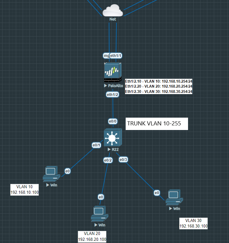
This topology looks a lot similar to Router-on-a-stick and behaves pretty much the same.
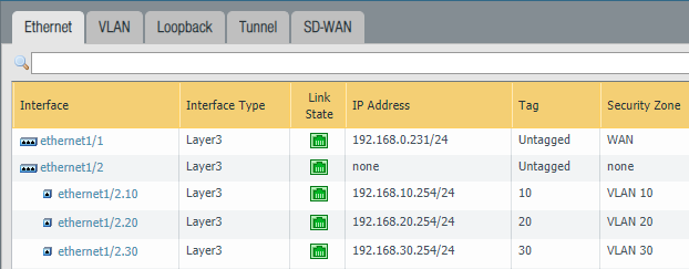
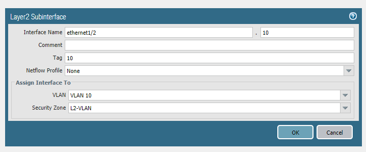
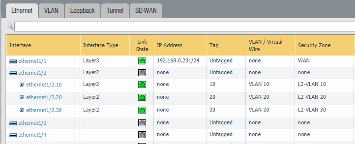
First, configure the parent interface Ethernet 1/2 as a Layer 2 interface and that’s the only thing that should be on the parent interface. Add sub-interfaces with VLAN 10, 20 and 30. Be specific with your naming, call the security zone L2-VLAN 10. Repeat the same for VLAN 20 and VLAN 30.
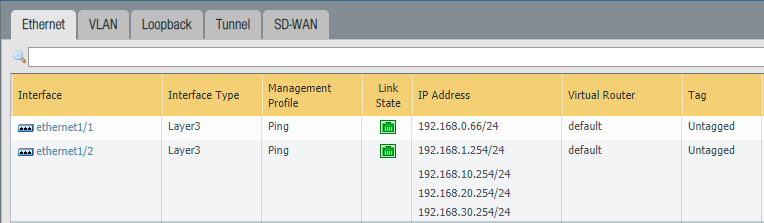
The final configuration on the tab ‘Ethernet’ should look like this:
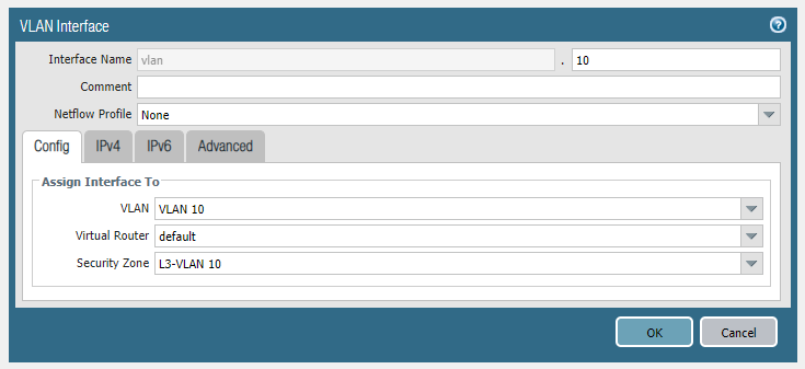
Head over to the VLAN tab and add a new VLAN interface. This time name the security zone “L3-VLAN 10“. Do the same for VLAN 20 and VLAN 30.
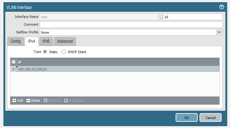
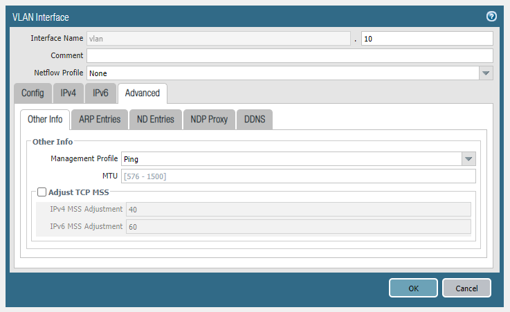
Enter 192.168.10.254/24 as the IPv4 address and add a ping management profile under the advanced tab. Repeat the same for VLAN 20 and VLAN 30.
Configure the physical interface e0/0 on the switch as a trunk port. E0/0 is the interface that connects with the parent interface Ethernet1/2 on the firewall.
Switch(config)#int e0/0
Switch(config-if)#switchport trunk encapsulation dot1q
Switch(config-if)#switchport mode trunk
Switch(config-if)#switchport trunk allowed vlan 10-255
Switch(config-if)#switchport trunk native vlan 3000
Switch(config-if)#no shutdown
Configure a physical interface as an Access port with VLAN 10 as ID. Repeat the same process for VLAN 20 and VLAN 30.
Switch(config)#int e0/1
Switch(config-if)#sw mode access
Switch(config-if)#sw access vlan 10
Switch(config-if)#no shutdown
Now it’s just a matter of putting the security policies in place and performing NAT.