L2 bridging enables us to migrate VM’s from a classic VDS port group to an overlay-segment. It’s useful to migrate physical workloads to NSX-T in the shape of an overlay-segment. With physical workloads we mean VM’s that are directly connected to a physical upstream router. It’s essentially a 1:1 relationship between VLAN & overlay transport zones.
Prerequisites
- NSX-T infrastructure up and running
- NSX Edges on a trunk link, either VDS or VLAN-backed segment
- Adding a VLAN sub-interface on the physical router for testing purpose
- Two VM’s, one connected with a classic VDS port group to the physical router
Topology
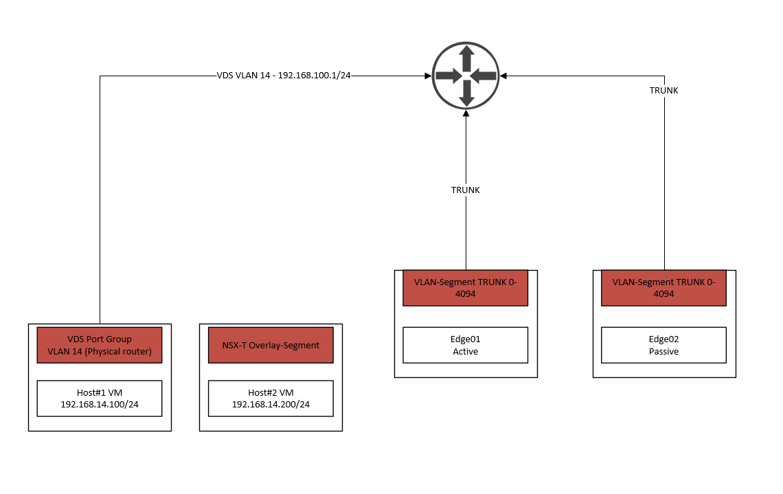
As we can see, the two edge nodes are using VLAN-segments instead of VDS port groups because it’s an inter-TEP communication setup between our TN’s and Edge nodes. If the TN and Edge nodes aren’t using the same subnet for their respective TEP addresses, then it’s not an inter-TEP setup and the trunk link will be a classic VDS port group instead.
For this demonstration we’ve added the VLAN 14 sub-interface on the upstream router. As we can see on the far left, Host#1 is directly connected to the physical router. When Host#1 generates traffic, it hits the default gateway of the physical router (192.168.100.1/24) and does not participate in the NSX-T infrastructure at all.
Host#2 will use an overlay-segment instead and should be able to communicate with Host#1. When Host#2 tries to communicate with Host#1, it’ll go through the NSX Edge first where it’ll be translated to VLAN 14 and back to the physical router. The router will forward it to Host#1 using its already existing routing table.
As we’ve noticed, there’s no need to change any of our routing configuration and it’s a seamless migration without any downtime.
The reason why we are using NSX Edges to translate is because ToRs are yet to support the GENEVE protocol. It used to be done with ESXI based L2 bridging but that’s deprecated as of now.
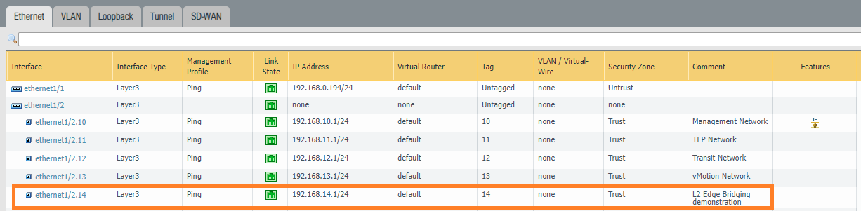
Adding the sub-interface VLAN 14
Instead of using any of our existing interfaces for this demonstration, we’ve decided to just create a new sub-interface which makes a lot more sense for this demonstration.
Edge uplink interfaces preparation
If you are using VDS port groups for your Edge node VM’s, then enable promiscuous mode and forged transmits.

If you are using VLAN-backed segments for your Edge node VM’s, which is the case for inter-TEP communication setups – enable the feature MAC learning by creating a new MAC discovery profile.
Networking > Connectivity > Segments
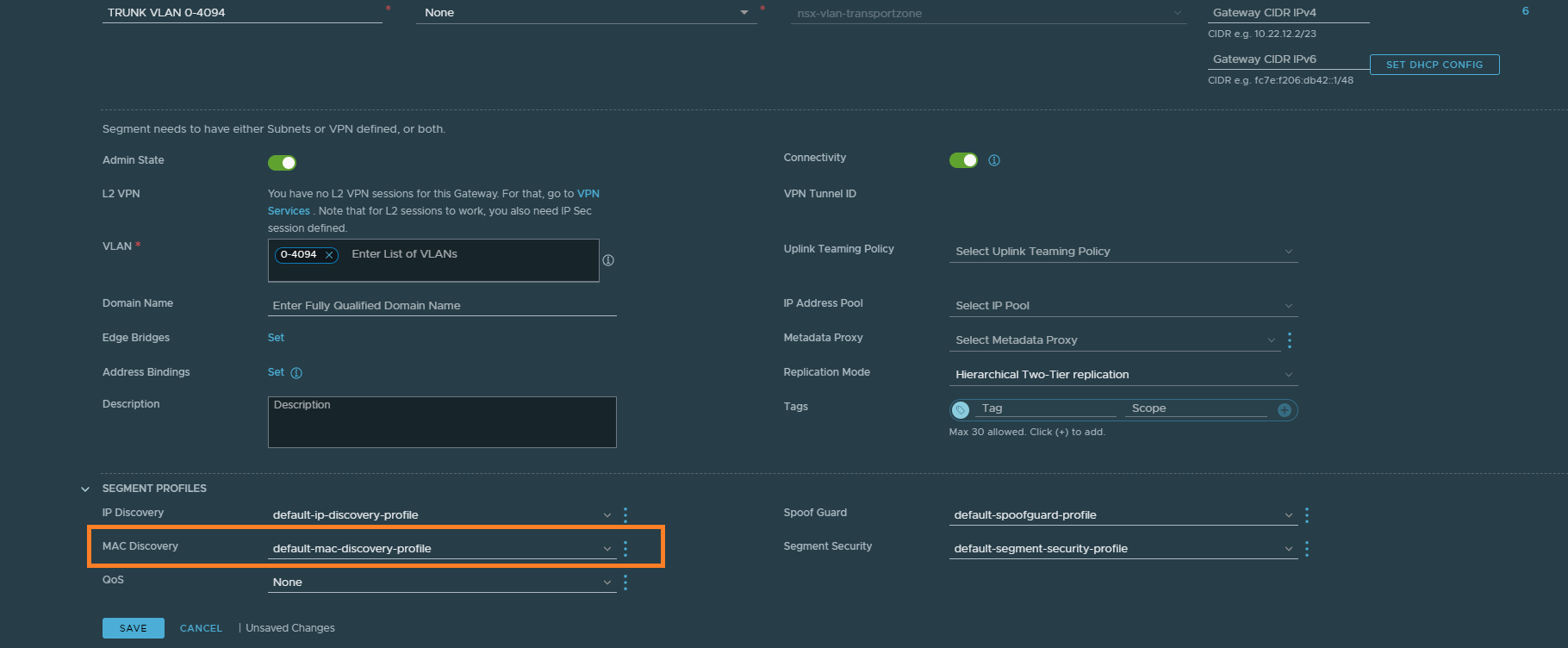
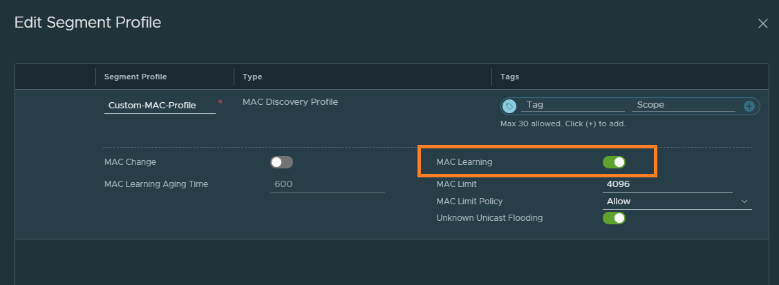
Just enable MAC learning and that’s all there is to it.
Creating Edge bridge profiles and segments
We’ll have to create the Edge bridge profile first before we can proceed.
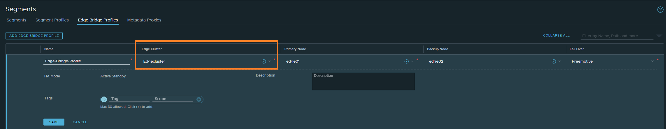
Networking > Connectivity > Segments > Edge Bridge Profiles
Our Edge cluster is configured as an active/passive pair. Preemptive mode is basically to assure that the primary node becomes the active unit again after coming back up.
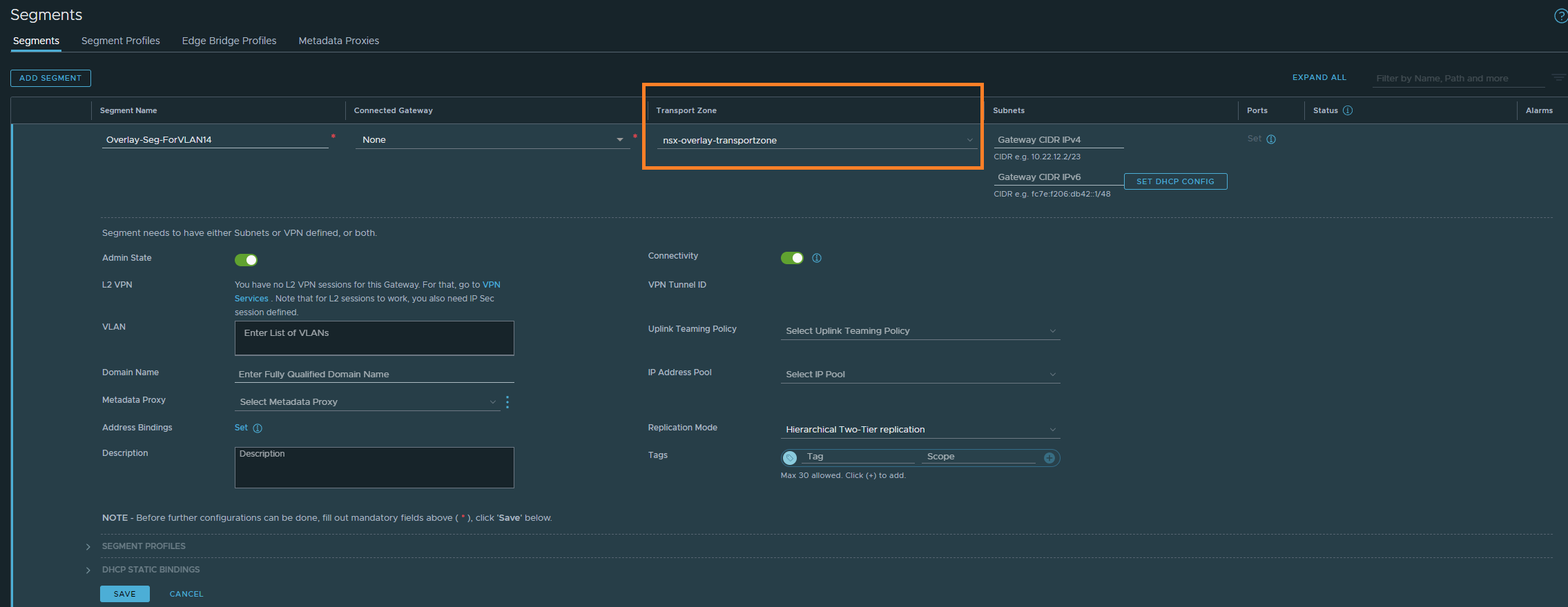
Networking > Connectivity > Segments
Next, we’ll create the overlay segment for VLAN 14. Select the overlay transport zone profile and hit save.
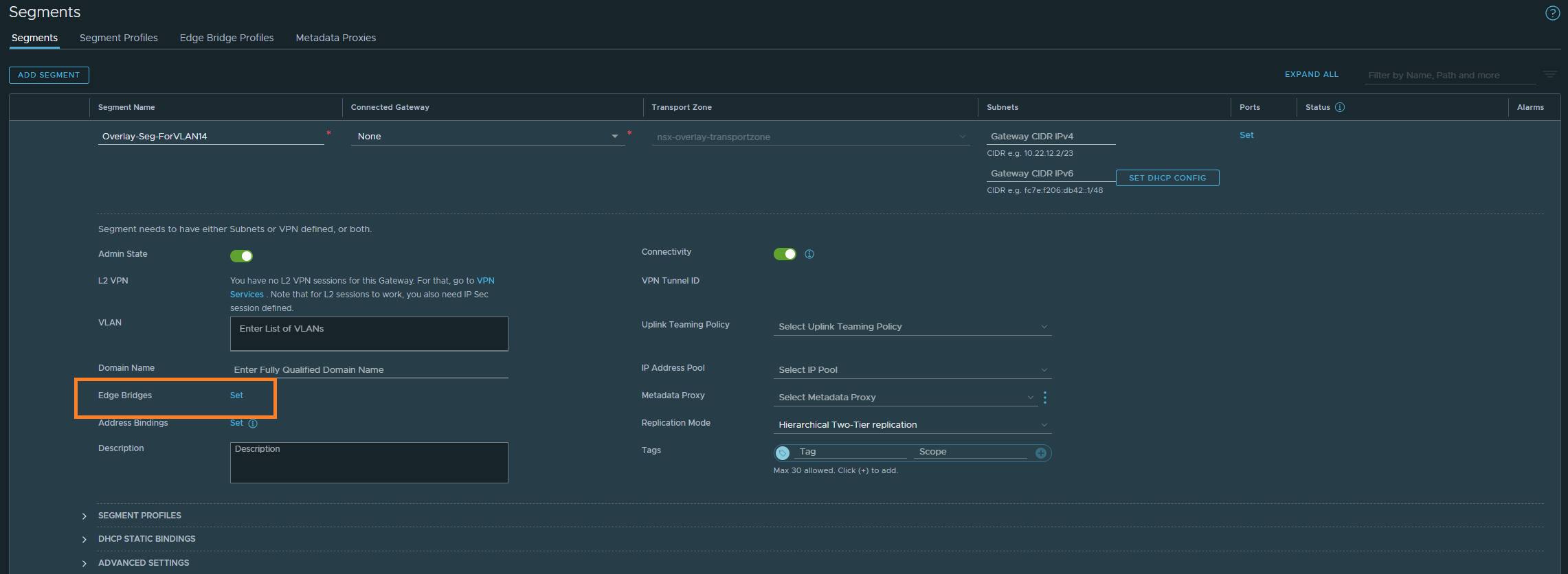
After saving, edit the segment and you’ll be able to configure ‘Edge Bridges’ as shown below.
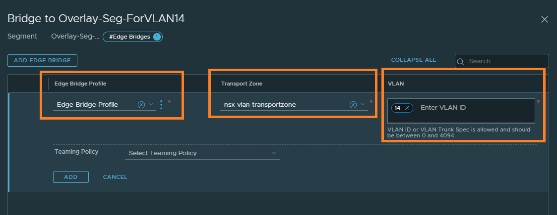
Select the Edge bridge profile we created, the VLAN transport zone this time and the VLAN ID.
At this point, update Host#2’s NIC to use the overlay-segment we just created. Host#1 and Host#2 should be able to communicate with each other or any other network.