
VRF’s mimic the concept of VLAN’s which break a switch into multiple ‘virtual’ switches or more specifically broadcast domains. VLAN’s operate at layer 2, so hosts with different VLAN tags are isolated from each other but isolation is lost with the addition of a router. That’s because traffic will be routed from one broadcast domain to another.
To introduce segmentation at layer 3, we can use VRF’s. VRF’s are essentially virtual routers and each of them have their own routing table. When we’re not using VRF’s, then we’re referring to the global routing table which is the default behavior.
Topology
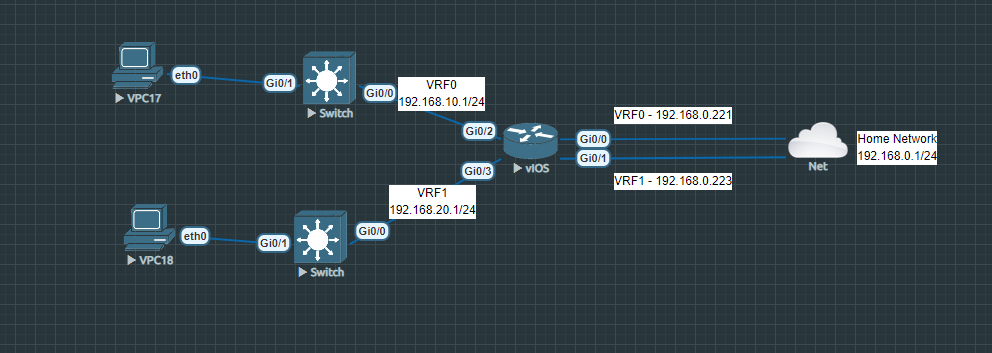
We have to VRF instances; VRF0 & VRF1. VRF0 with an inside network of 192.168.10.0/24 that’s translated to an outside address of 192.168.0.221. VRF1 with an inside network of 192.168.20.0/24 that’s translated to an outside address of 192.168.0.223. The global routing instance will not be used for this demonstration.
Configuration
Let’s kick it off by creating both VRF’s. We’ll name it accordingly to our topology and we have to specify IPv4 as the address type.
Router>en
Router#conf t
Router(config)#vrf definition vrf0
Router(config-vrf)#address-family ipv4
Router(config-vrf-af)#exit
Router(config-vrf)#vrf definition vrf1
Router(config-vrf)#address-family ipv4
Router(config-vrf-af)#exit
Router(config-vrf)#exit
Next, we’ll configure our outside interfaces. If there’s already an IP address assigned to the interface, it will automatically migrate to the VRF instance. VRF0 will be linked to g0/0 and VRF1 to g0/1.
Router(config)#int g0/0
Router(config-if)#vrf forwarding vrf0
Router(config-if)#ip address 192.168.0.221 255.255.255.0
Router(config-if)#ip nat outside
Router(config-if)#no shutdown
Router(config-if)#exit

Router(config)#int g0/1
Router(config-if)#vrf forwarding vrf1
Router(config-if)#ip address 192.168.0.223 255.255.255.0
Router(config-if)#ip nat outside
Router(config-if)#no shutdown
Router(config-if)#exit
And we’ll configure our inside interfaces. VRF0 will be linked to g0/2 and VRF1 to g0/3.
Router(config)#int g0/2
Router(config-if)#vrf forwarding vrf0
Router(config-if)#ip address 192.168.10.1 255.255.255.0
Router(config-if)#ip nat inside
Router(config-if)#no shutdown
Router(config-if)#exit

Router(config)#int g0/3
Router(config-if)#vrf forwarding vrf1
Router(config-if)#ip address 192.168.20.1 255.255.255.0
Router(config-if)#ip nat inside
Router(config-if)#no shutdown
Router(config-if)#exit
We’ll have to add a default route for each of our VRF instance. It has to point to 192.168.0.1 which is the next-hop and the default-gateway of my upstream network.
Router(config)#ip route vrf vrf0 0.0.0.0 0.0.0.0 192.168.0.1
Router(config)#ip route vrf vrf1 0.0.0.0 0.0.0.0 192.168.0.1
With the following command we can request the routing table for VRF0 and VRF1.
Router(config)#do show ip route vrf vrf0

Routing Table: vrf0
Codes: L - local, C - connected, S - static, R - RIP, M - mobile, B - BGP
       D - EIGRP, EX - EIGRP external, O - OSPF, IA - OSPF inter area
       N1 - OSPF NSSA external type 1, N2 - OSPF NSSA external type 2
       E1 - OSPF external type 1, E2 - OSPF external type 2
       i - IS-IS, su - IS-IS summary, L1 - IS-IS level-1, L2 - IS-IS level-2
       ia - IS-IS inter area, * - candidate default, U - per-user static route
       o - ODR, P - periodic downloaded static route, H - NHRP, l - LISP
       a - application route
       + - replicated route, % - next hop override, p - overrides from PfR

Gateway of last resort is 192.168.0.1 to network 0.0.0.0

S*    0.0.0.0/0 [1/0] via 192.168.0.1
      192.168.0.0/24 is variably subnetted, 2 subnets, 2 masks
C        192.168.0.0/24 is directly connected, GigabitEthernet0/0
L        192.168.0.221/32 is directly connected, GigabitEthernet0/0
      192.168.10.0/24 is variably subnetted, 2 subnets, 2 masks
C        192.168.10.0/24 is directly connected, GigabitEthernet0/2
L        192.168.10.1/32 is directly connected, GigabitEthernet0/2
Router(config)#do show ip route vrf vrf1

Routing Table: vrf1
Codes: L - local, C - connected, S - static, R - RIP, M - mobile, B - BGP
       D - EIGRP, EX - EIGRP external, O - OSPF, IA - OSPF inter area
       N1 - OSPF NSSA external type 1, N2 - OSPF NSSA external type 2
       E1 - OSPF external type 1, E2 - OSPF external type 2
       i - IS-IS, su - IS-IS summary, L1 - IS-IS level-1, L2 - IS-IS level-2
       ia - IS-IS inter area, * - candidate default, U - per-user static route
       o - ODR, P - periodic downloaded static route, H - NHRP, l - LISP
       a - application route
       + - replicated route, % - next hop override, p - overrides from PfR

Gateway of last resort is 192.168.0.1 to network 0.0.0.0

S*    0.0.0.0/0 [1/0] via 192.168.0.1
      192.168.0.0/24 is variably subnetted, 2 subnets, 2 masks
C        192.168.0.0/24 is directly connected, GigabitEthernet0/1
L        192.168.0.223/32 is directly connected, GigabitEthernet0/1
      192.168.20.0/24 is variably subnetted, 2 subnets, 2 masks
C        192.168.20.0/24 is directly connected, GigabitEthernet0/3
L        192.168.20.1/32 is directly connected, GigabitEthernet0/3
We’ll be creating two DHCP pools, one for VRF0 and VRF1. This step is optional and statically configuring your clients is just fine for testing purposes.
Router(config)#ip dhcp pool vrf0
Router(dhcp-config)#network 192.168.10.0 255.255.255.0
Router(dhcp-config)#default-router 192.168.10.1
Router(dhcp-config)#dns-server 8.8.8.8
Router(dhcp-config)#vrf vrf0
Router(dhcp-config)#exit


Router(config)#ip dhcp pool vrf1
Router(dhcp-config)#network 192.168.20.0 255.255.255.0
Router(dhcp-config)#default-router 192.168.20.1
Router(dhcp-config)#dns-server 8.8.8.8
Router(dhcp-config)#vrf vrf1
Router(dhcp-config)#exit
Finally, we’ll configure NAT so that the clients can reach the internet. First, we’ll create a standard ACL with a wildcard mask for each of our inside networks.
Router(config)#access-list 1 permit 192.168.10.0 0.0.0.255
Router(config)#access-list 2 permit 192.168.20.0 0.0.0.255
Next, we’ll create the NAT policy referencing to the ACL we just created earlier.
Router(config)#ip nat inside source list 1 interface g0/0 vrf vrf0 overload
Router(config)#ip nat inside source list 2 interface g0/1 vrf vrf1 overload
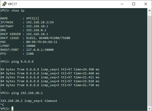
Our clients should be able to hit the internet and not be able to ping each other. 192.168.10.0/24 in VRF0 should not be able to communicate with 192.168.20.0/24 in VRF1.
VRF0 – 192.168.10.0/24:
VRF1 – 192.168.20.0/24:
