GlobalProtect Satellite allows you to quickly deploy site-to-site tunnels in a matter of seconds. It simplifies the deployment process because there isn’t a lot to configure on the other side of the tunnel. Although the initial configuration of setting the Portal and Gateway up takes quite a bit of time, but that’s a one time procedure. Configuring the satellites take little to no effort, just simply add the portal address and the phase 2 IPSEC tunnels will be advertised from the gateway.
IPSEC site-to-site can be troublesome, especially in a larger environment with a lot of phase 1 and phase 2 tunnels and when more tunnels are added as time moves forward. IPSEC phase 2 tunnel we all are aware of:
HQ: 192.168.70.0/24 (Local) -> 192.168.150.0/24 (Remote)
Branch: 192.168.150.0/24 (Local) -> 192.168.70.0/24 (Remote)
We all have had our headaches with ipsec tunnels and it’s getting more difficult to manage them as we add more tunnels. GlobalProtect Satellite simplifies this by simply just having the option to advertise your networks you want to participate in the IPSEC tunnel – without having knowledge of the other side of the tunnel.
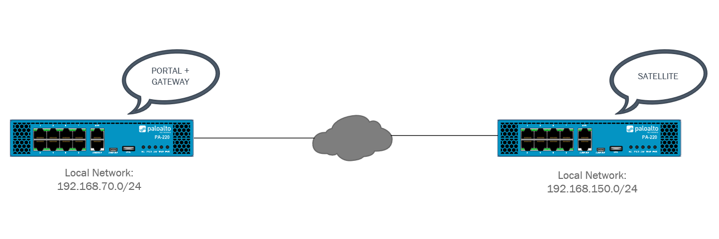
Topology
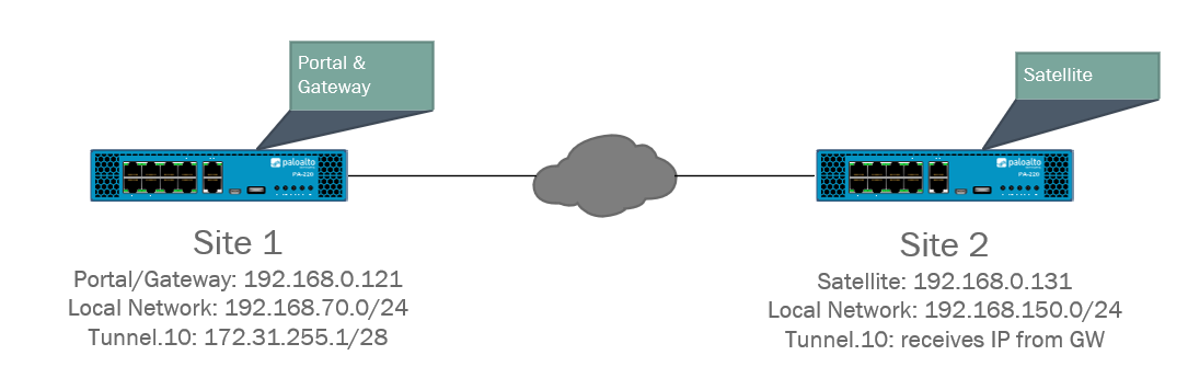
The concept should come as no surprise that it’s very similar to IPSEC site-to-site. Site 1 (HQ) will have the portal and gateway installed on the same interface and an IP-address of 192.168.0.121 at ethernet1/1 which is an outside interface. The Satellite on Site 2 (Branch) will also be configured on the outside interface at ethernet1/1 with 192.168.0.131 as the IP-address.
However with Palo Alto NGFW’s we need to use tunnel interfaces for our VPN services (with internal GW being an exception). We’ll add an IP-address of 172.31.255.1/28 to our Tunnel.10 interface on Site 1 (HQ). We do not need to add an IP-address to the Tunnel.10 interface on Site 2 (Branch) because the gateway will hand one out, although it’s fine to add one manually.
Lastly we have two LAN networks: Site 1 (HQ) 192.168.70.0/24 and Site 2 (Branch) 192.168.150.0/24. VLAN’s were used to create the LAN networks but this is not mandatory.
Prerequisites
- Prior experience with IPSEC site-to-site tunnels
- Understanding of how certificates work
- 2x GlobalProtect Licenses
- 2x Palo Alto NGFW’s
- 2x LAN networks
Changes since PAN-OS 10.1
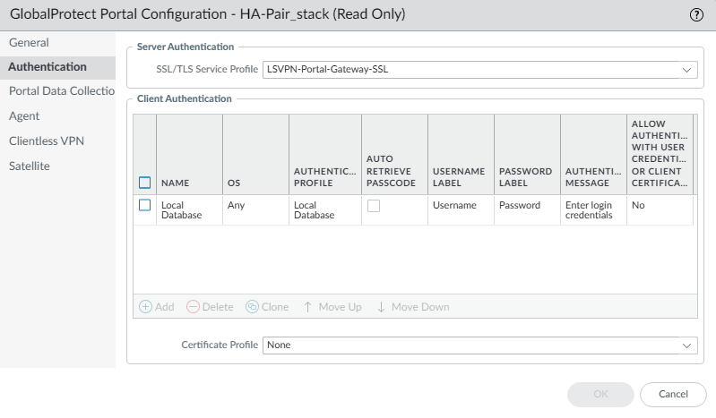
Since the release of PAN-OS 10.1 there’s an additional method of authentication introduced. It’s required and when you would connect the satellite to the portal – it’ll ask the credentials. I simply used the local database and created a username called “LS-VPN”. Create the username under Device > Local User Database > Users. Just make sure that you select the “Local Database” as the authentication method for your portal.
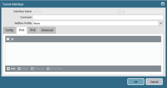
Tunnel interfaces
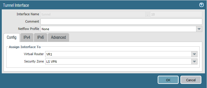
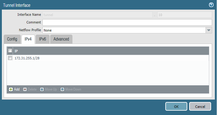
Site 1 (HQ – Portal/Gateway) Tunnel.10 interface
Assign LS VPN as Security Zone and the Virtual Router you use for all of your purposes.
Specify the IPv4 address and your subnet mask of choice.
Site 2 (Branch – Satellite) Tunnel.10 interface

We can specify an IP-address here but there’s no need because the Gateway will assign one to this tunnel interface.
Security Policies
Site 1 (HQ – Portal/Gateway)
Let’s configure our security policies beforehand so we don’t forget about it down the road. Click on the picture for a better view.
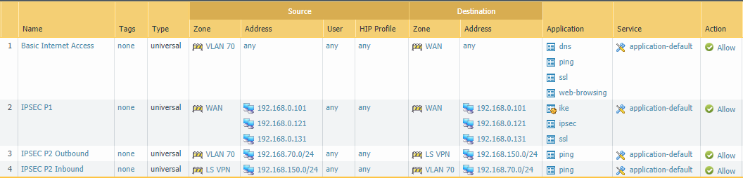
The IPSEC Phase 1 rule is strictly for the outside interfaces of both the firewalls at Site 1 & Site 2. We’ll need to allow IKE & IPSEC applications to establish the tunnels and add SSL because GlobalProtect Satellite use TLS certificates as authentication method and uses OCSP to validate whether or not the certificates/devices are valid.
The Phase 2 rule will be bidirectional either VLAN 70 or LS VPN (=VLAN 150 192.168.150.0/24) can initiate the connection.
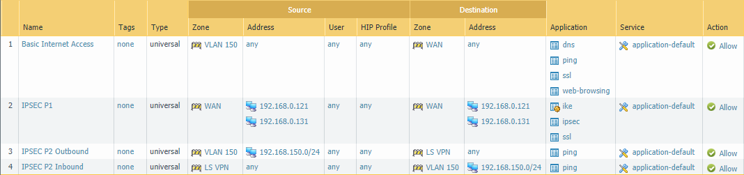
Site 2 (Branch – Satellite)
The IPSEC Phase 1 rule here is identical as the one at Site 1. The Phase 2 rule is slightly different except that the IP-address for LSVPN is obviously 192.168.70.0/24 and the local network is VLAN 150 192.168.150.0/24.
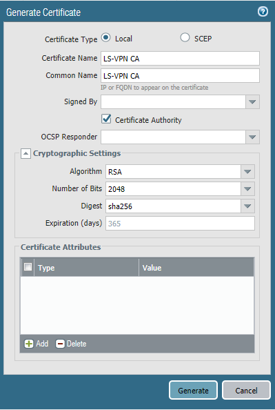
Certificates
Site 1 (HQ – Portal/Gateway)
Because we need to issue certificates to satellites we need a certificate in the form of an CA to do this. Some public webserver certificate can’t issue certificates. Either we use a self-signed CA or use our Active Directory’s CA but the latter is more complex because it requires a SCEP profile. To keep it simple we’ll use a self-signed CA.
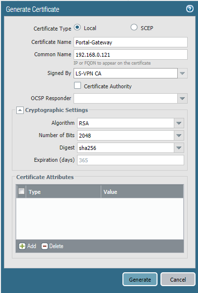
Check “Certificate Authority” so it can issue certificates and the other settings don’t matter for a self-signed certificate anyways. Do this on Site 1 (HQ – Portal/Gateway)
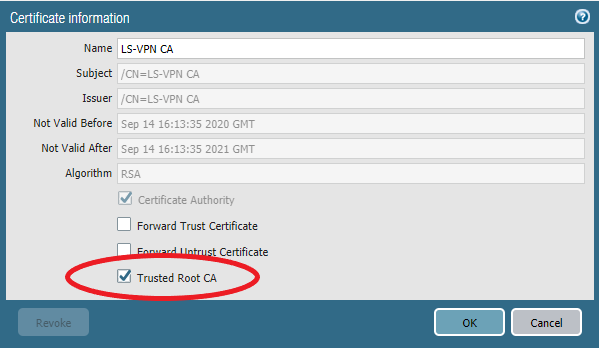
Let’s request a certificate for the Portal and Gateway. We can use the same certificate and the SSL/TLS Service profile for both instances. Make sure to not check the checkbox “Certificate Authority” and have our LS-VPN CA self-signing the certificate.
Make sure to set it as a “Trusted Root CA”

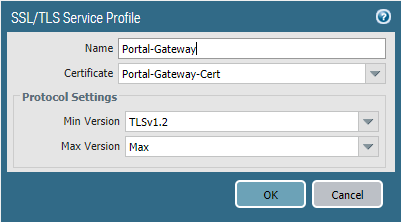
Next we need a SSL/TLS Service Profile for the Portal & Gateway to use. Device > Certificate Management > SSL/TLS Service Profile and use the Portal-Gateway Certificate.
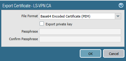
Our self-signed CA certificate should be exported from the Site 1 firewall (HQ). The private key does not have to be exported.
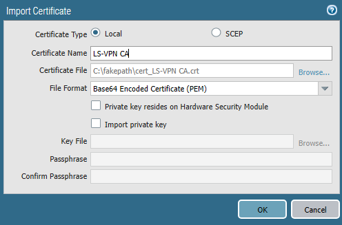
And then it should be imported on the firewall at site 2 which is the satellite.
Again make sure it’s checked as a “Trusted Root CA”.
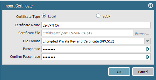
Site 2 (Branch – Satellite)
Import the certificate on the firewall at Site 2 and enter the passphrase.
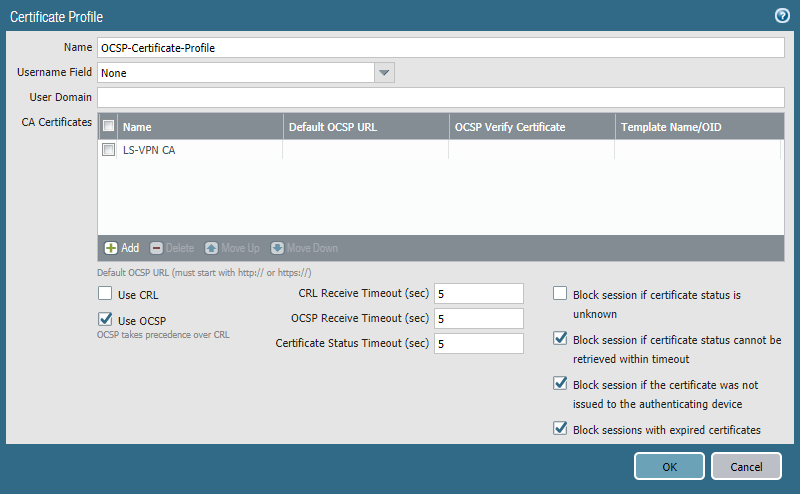
OCSP (Site 1 only)
Device > Certificate Management > Certificate Profile
OCSP checks whether a certificate is valid or not and with a certificate profile we do have more control over which devices are allowed. We only need it at Site 1 (HQ).
Create a certificate profile that includes the self-signed CA with OCSP enabled. We’ll use this certificate profile later on when configuring the gateway.
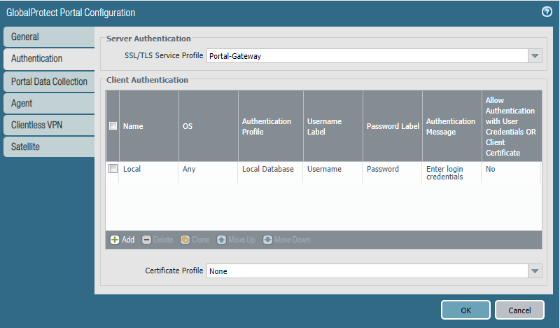
Portal configuration (Site 1 only)
Network > GlobalProtect > Portal
Select the outside interface and in my case it’s ethernet1/1 and 192.168.0.121
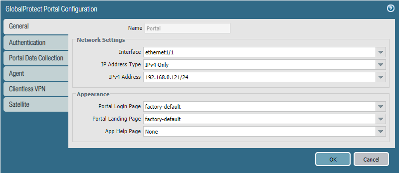
Select the SSL/TLS Service Profile we made for the Portal-Gateway. Create a local user database and it really doesn’t matter what’s in it.
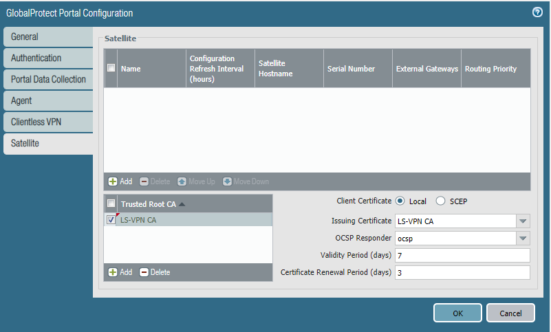
Add the LS-VPN CA as Trusted Root CA. Select LS-VPN CA as the issuing certificate and the OCSP responder profile we created.
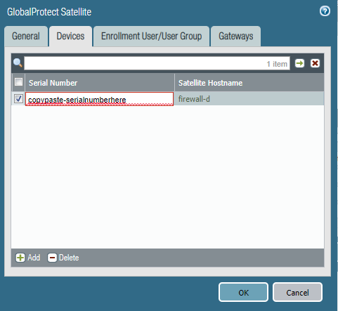
Add a Satellite and enter the Serial Number of the firewall of Site 2. Eventually the hostname of that firewall will resolve.
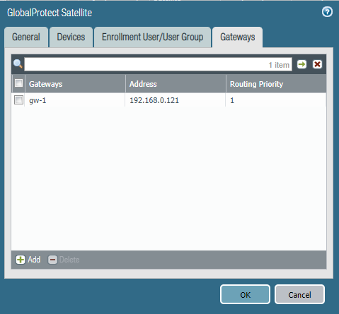
We only have one gateway and it’s at the same interface/IPv4 as the Portal. For future reference; a lower routing priority value has a higher priority.
Gateway configuration (Site 1 only)
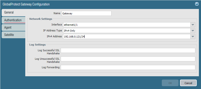
Network > GlobalProtect > Gateway
Add a new one and use the same interface and IPv4 address as the portal.
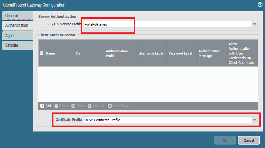
Use the same SSL/TLS Service Profile and this time add the certificate profile which includes the self-signed CA and the OCSP settings. We do not need to include an authentication profile here.
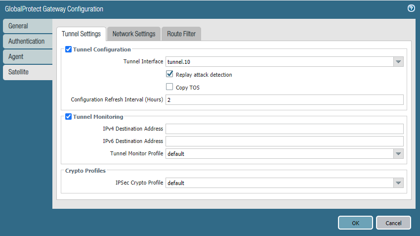
In the Satellite tab, select Tunnel.10 as the interface and pick the default tunnel monitor profile. The default IPSec Crypto Profile should do although consider changing it.
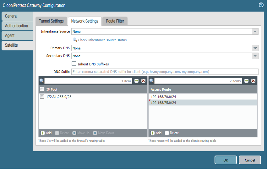
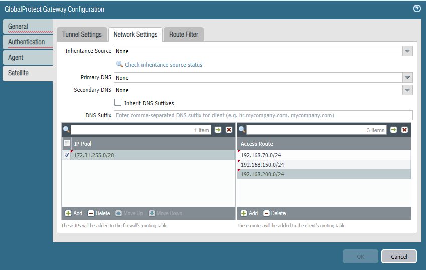
Under Network Settings, the IP Pool is actually the range of IP-addresses the Gateway will lease out to other tunnel interfaces like on Site 2. For Access Route we have to define which networks we want to include in the tunnel which obviously is just VLAN 70. If we’re ever expanding and we want to include a new network, we simply add it to our access routes.

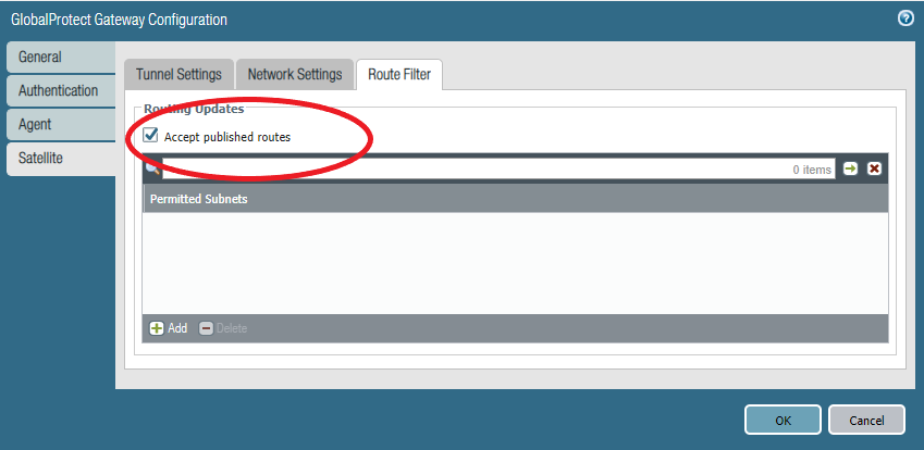
Under Route Filter check “Accept published routes” so it learns the routes from the Satellite of Site 2.
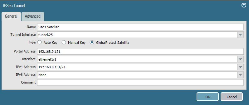
Satellite Configuration (Site 2 only)
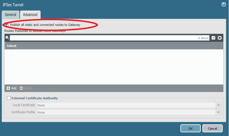
Network > IPSEC Tunnels
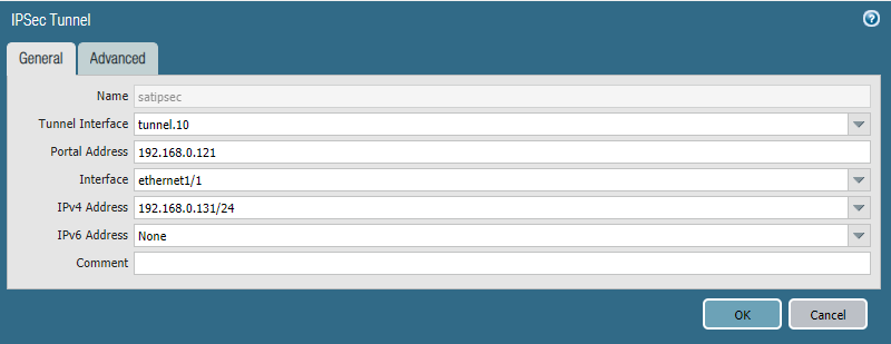
Under Advanced check “Publish all static and …” so the Satellite advertises its routes to the gateway.
Verifying from Site 2 (Satellite)
If you’re noticing that the portal connection fails because it requires credentials, it’s likely that you’re using PAN-OS 10.1 or above. See the beginning of this article for what you’ll have to do.
To verify that everything works as intended the obvious method is a ping from both directions.
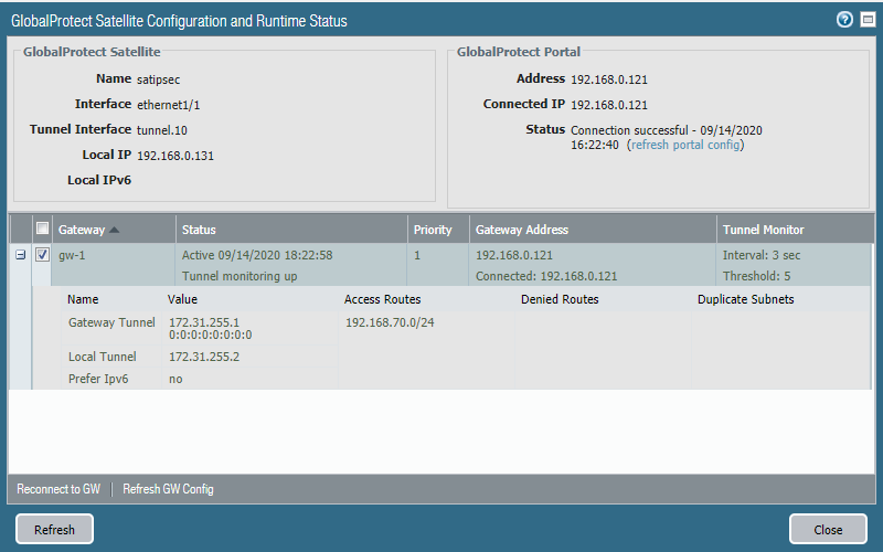
On the Satellite (Network > IPSEC Tunnels) we can see the access routes and the IP-address of the peer’s tunnel interface and the local tunnel interface.
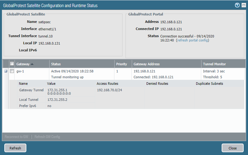
We can also see the routes (published by the Virtual Router). Traffic has to be routed first to 172.31.255.1 (Site 1 Tunnel interface IP) before it can reach the destination network 192.168.70.0/24.
Verifying from Site 1 (HQ)
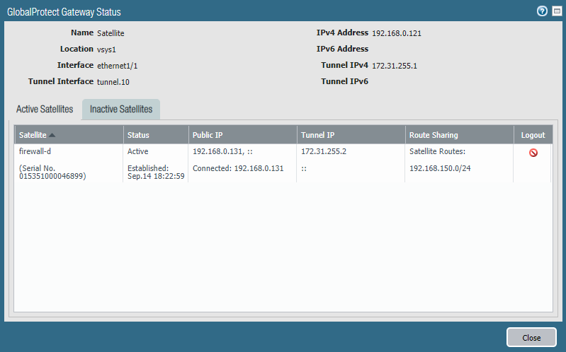
We can see the active and inactive Satellites under Network > GlobalProtect > Gateway
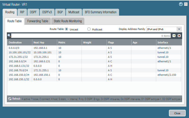
Head over to Network > Virtual Routers > More Runtime Stats to see the active routes.
We can see that the next hop for the destination network 192.168.150.0/24 is 172.31.255.2 which is the tunnel interface on Site 2.

The magic: adding a new network
This is where Large-Scale VPN shines because it’s so quick and easy to do. Simply just add the network under Access Routes in the Gateway. I’ll add VLAN 75 (192.168.75.0/24) as an example.
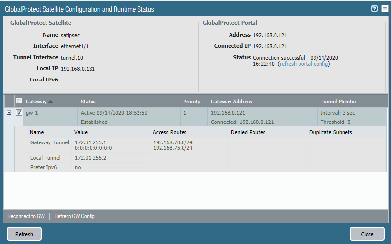
We also have to update our security policies so that traffic from and to VLAN 75 (192.168.75.0/24) is allowed. Next, head over to the Satellite on Site 2 and click the “reconnect to GW” button and then refresh.
And we can see that the access routes are updated.
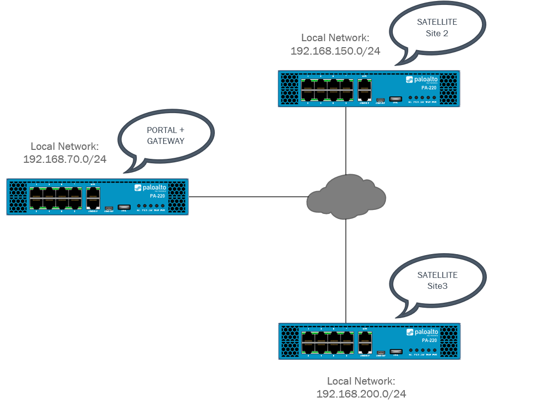
What if we want to add another Site?
Currently we just have a basic single gateway and satellite configuration between two sites.
Let’s say the company is expanding and we want to add another branch office to connect with Site 1 & Site 2. For this example Site 3 will have a local network of 192.168.130.0/24.
Simply repeat Site2’s Satellite configuration for Site 3.
And under Advanced check “Publish all static…”
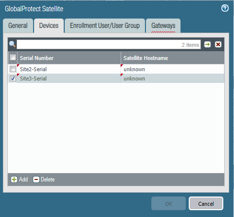
Make sure to include the serial number of Site 3’s Firewall at the Portal.
In order for Site 2 and Site 3 to communicate through the GlobalProtect Gateway we have to include their local networks in the Gateway’s Access Route table. And in our case, it’s 192.168.150.0/24 (Site 2) & 192.168.200.0/24 (Site 3).
Try to refresh the gateway connection over at Site 2 if you’re running into issues. At this point Site 1 should be able to communicate with Site 2 and Site 3 in both directions. Site 2 should also be able to communicate with Site 3 and vice versa.