VMware NSX is quite difficult to pick up because it’s completely different to traditional networking which is referred to as the underlay or physical network. Basically what NSX does is adding another layer on top of the existing underlay network and hence the terminology ‘overlay’. The physical/underlay network doesn’t need to know anything about the overlay network.
Overlay networks are just point to point connections between two endpoints and often just called VTEP (virtual tunnel endpoint) utilizing the VXLAN/GENEVE protocol. Not to be confused with an IPSEC tunnel because that’s entirely different.
NSX-T uses the GENEVE encapsulation protocol and this is the part that makes overlay networks happen. The older NSX-V uses the VXLAN protocol.
The benefits to VXLAN/GENEVE is that you can span your L2/VLAN zones across the WAN or over a layer 3 interface. So imagine if two VM’s have to think that they are in the same VLAN/subnet but they’re in different geographical locations. One in New York and Miami. Well that won’t happen with traditional networking – unless you stretch the network across the WAN. For example, a network 192.168.100.0/24 is present on both locations. Both VM’s will communicate using the TEP IP addresses and they’ll know what packets are destined for them based on the VNI (Virtual Network Identifier). VNI is like almost a VLAN ID, although not the same.
Another benefit is that you get up to 16M network segments compared to traditional VLAN’s at around ~4090’ish.
Prerequisites
- vCenter
- NSX-T unified appliance with a trial license
- Get the nested ESXI Appliance from https://www.virtuallyghetto.com/nested-virtualization/nested-esxi-virtual-appliance
- A firewall/router with BGP support
- DNS server for FQDN’s
- Carefully analyze my topology or you’ll run into issues
Topology

Basically what I’ve done here is placing a firewall between my home network and the NSX area. The idea was to visualize my home network as an ISP and that our Palo Alto firewall is the only thing we have our hands on. A nested ESXI host is used just because I do not have enough physical uplinks available. With a nested ESXI appliance we can just assign as many NIC’s as we want and have them function as an uplink.
Also an Active Directory server was used for DNS naming. A static route was added on my home router; 192.168.10.0/24 and next-hop 192.168.0.69 (Palo Alto’s WAN interface). That was done so that my home subnet 192.168.0.0/24 is aware of a possible route to 192.168.10.0/24 (the LAN network on the PA).
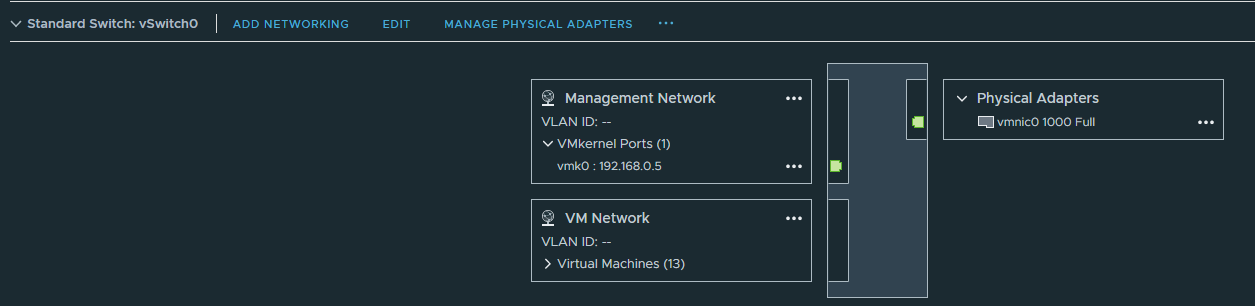
On our physical host, two switches are used. The first, vSwitch0 with the default VM Network port group and an uplink to my home network. This port group will be assigned to the WAN interface on the Palo Alto firewall.
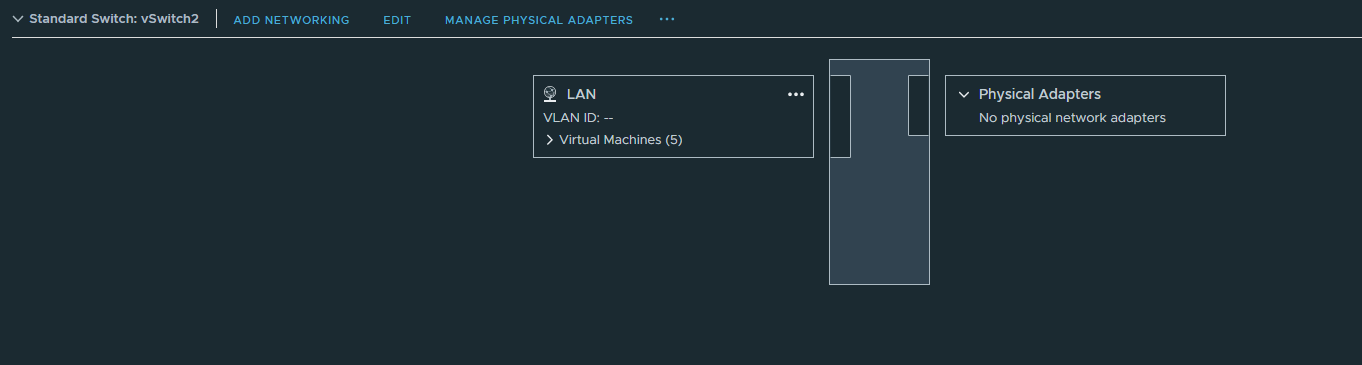
vSwitch2 has the port group “LAN” with no uplink at all, so it’s entirely isolated. We’ll use this port group for the LAN interface on the Palo Alto firewall.
The Palo Alto firewall will learn its routes from NSX Edge with BGP and advertise a default route to the Tier 0 gateway. We don’t have to configure NAT on NSX because the firewall already does it.
The nested ESXI host, NSX-T manager, NSX edge and the domain controller will use the “LAN” port group.
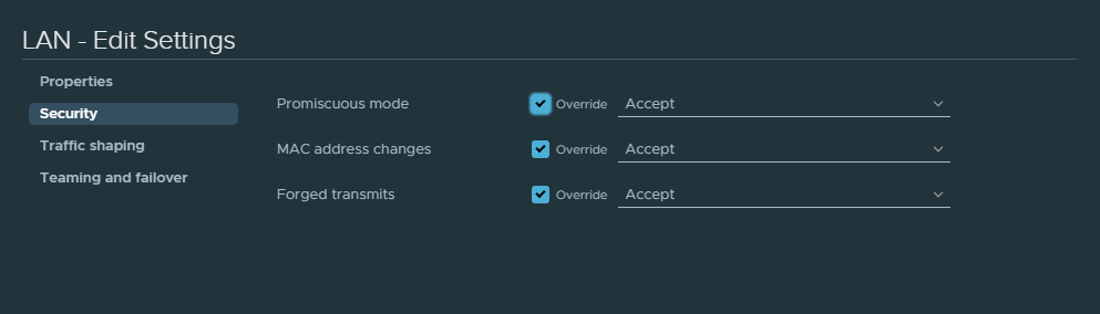
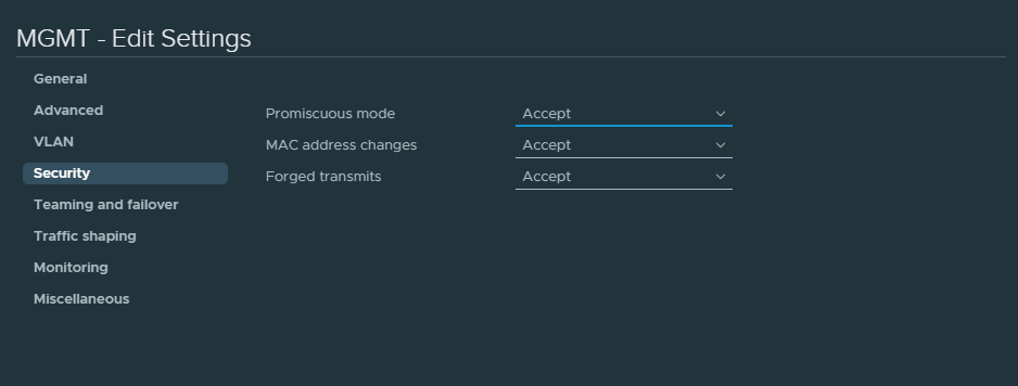
Accept the following security options for the “LAN” port group or else BGP might fail.
Finally, the nested ESXI host, NSX-T manager, NSX edge and the domain controller VM’s are installed on my physical ESXI host and not on the nested ESXI host. These can be installed on a nested ESXI host just fine, but at the costs of performance.
Where are the VM’s installed?
- Nested ESXI VM: physical host (VMHost 1)
- Domain Controller installed on: physical host (VMHost 1)
- NSX-T Manager: physical host (VMHost1)
- PAN Firewall: physical host (VMHost1)
- NSX Edge: physical host (VMHost1)
- Web-Segment CentOS 8: nested ESXI
- App-Segment CentOS 8: nested ESXI
Nested ESXI appliance & configuring dSwitch
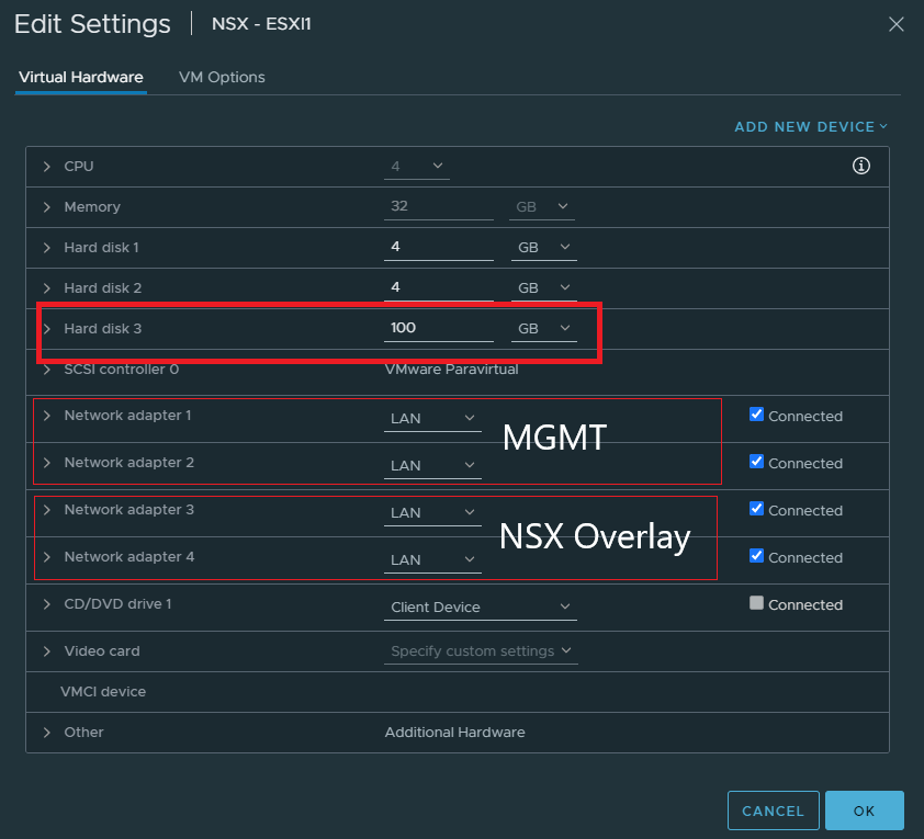
Increase the size of the 3rd hard disk. That’ll be necessary if we want to install a VM to test out NSX segments. NSX segments are simply NSX specific port groups that VM’s will use. It’ll make sense when we get there.
Add 4 NIC’s and the first two will be reserved for management purposes in a dSwitch. Because I haven’t done anything special with the 2nd NIC, it just functions as a failover link. The 3rd and 4th NIC is for NSX overlay which will be used either with NVDS or VDS switches later on.
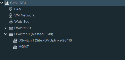
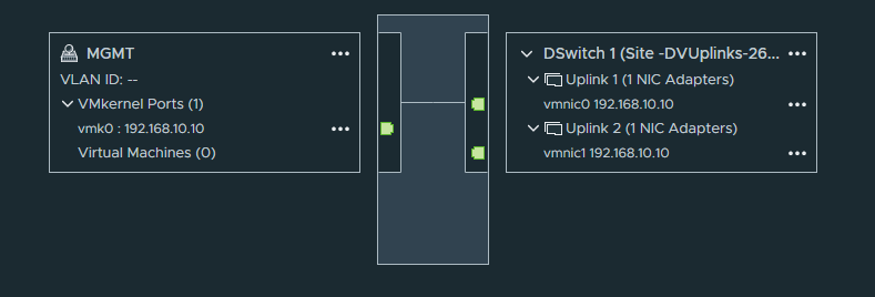
Create a dSwitch with 2 uplinks and a “MGMT” port group. Don’t bother with VLAN’s here.
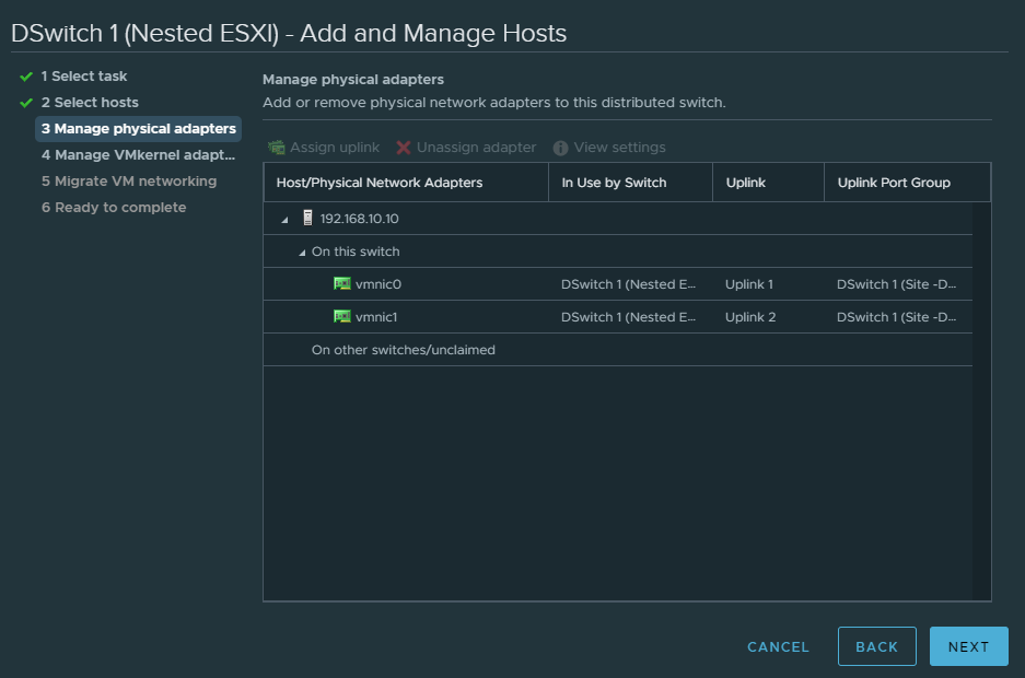
Assign the uplinks as shown below.
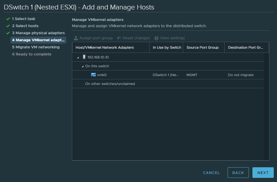
Assign VMK0 (VMware kernel adapter) the MGMT port group.
Also accept the following security options for the MGMT port group. Without this BGP might not work.
And finally the topology.
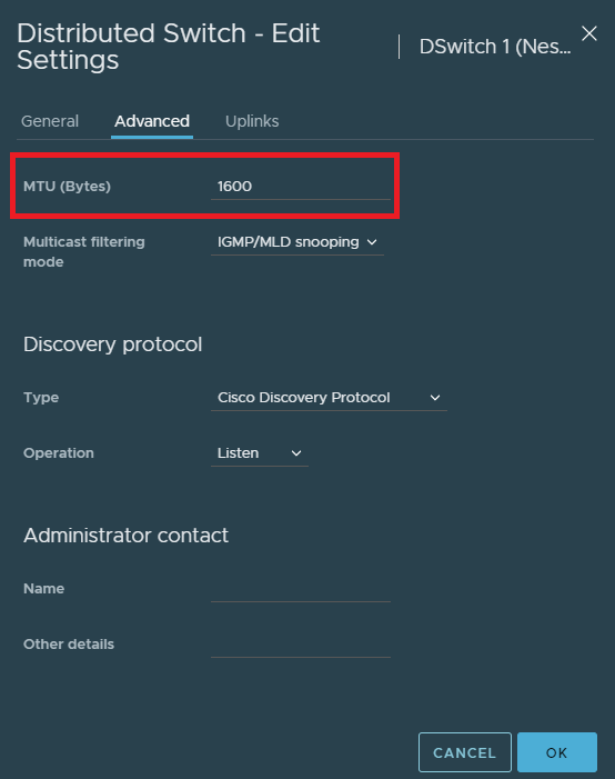
The last thing to do is to raise the MTU of the dSwitch to at least 1600.
Deploying NSX-T Manager
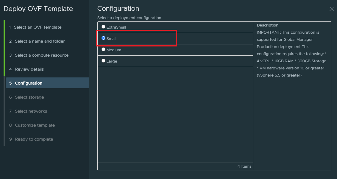
Deploy the NSX-T unified appliance and up until step 5 it’s pretty much self-explanatory. But you do have to select the small deployment here. Don’t select the extra small deployment because that’s for the NSX cloud service manager to run in a public cloud in addition to the regular NSX-T manager.
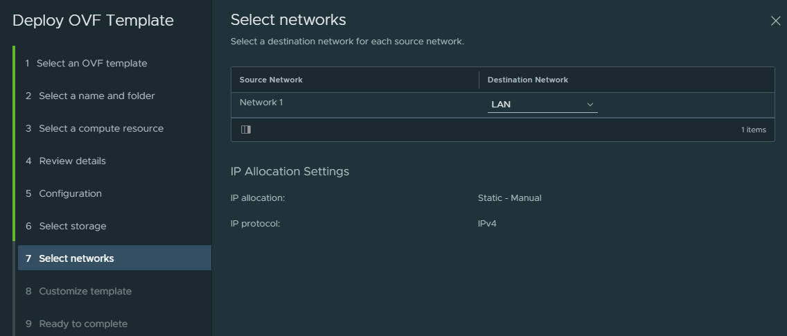
Select the “LAN” port group as the management interface for the NSX-T Manager.
The next step is to finish the configuration of IP addresses, DNS and passwords.
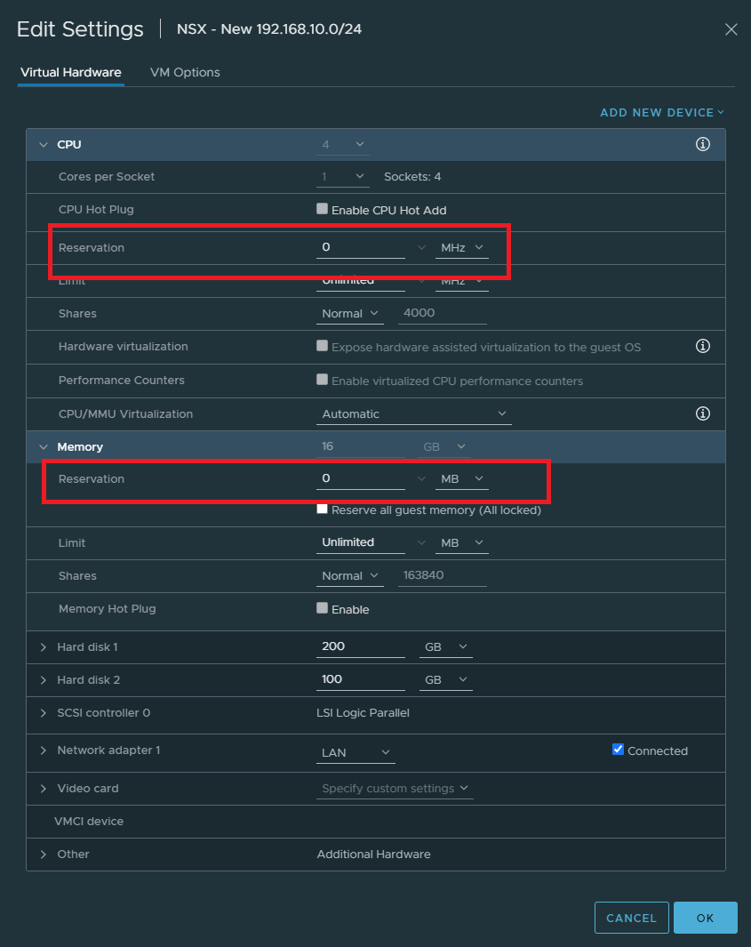
To save on resources, edit the VM settings and set the CPU & Memory reservations to 0.
NSX-T initial configuration
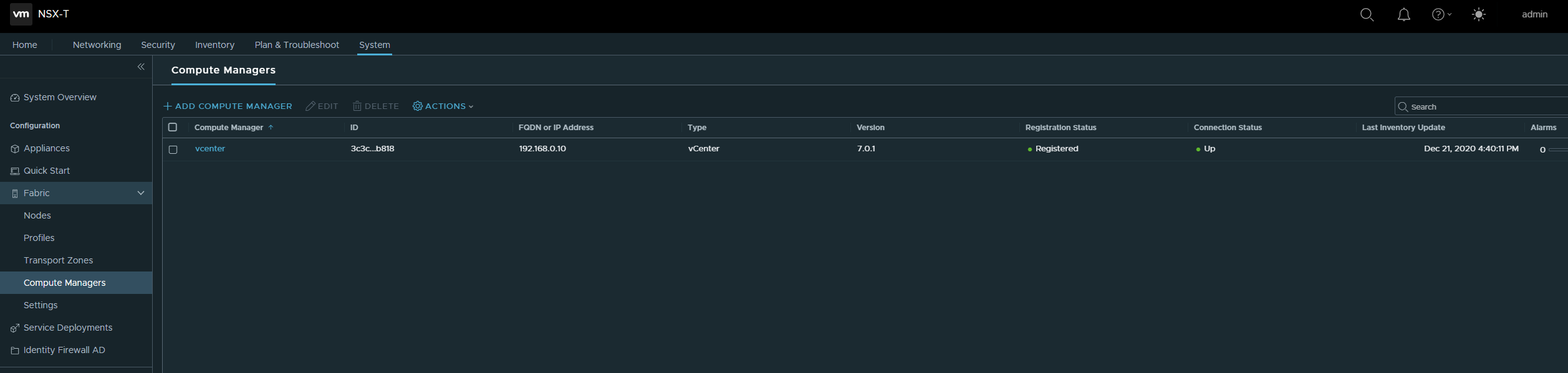
System > Fabric > Compute Managers
Let’s start off by adding a compute manager and in our case it’s vCenter.
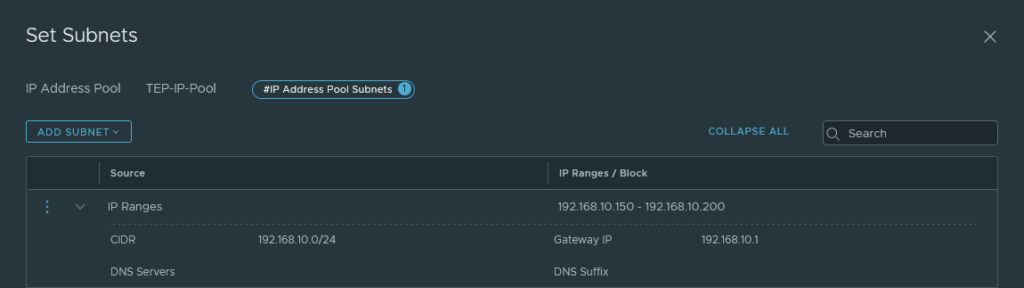
Networking > IP address pools
Create an IP address pool for TEP addresses. Either opt for a block or a range and it should be within the same range as the physical upstream network. In my case, it’s 192.168.10.0/24 (LAN Port group).
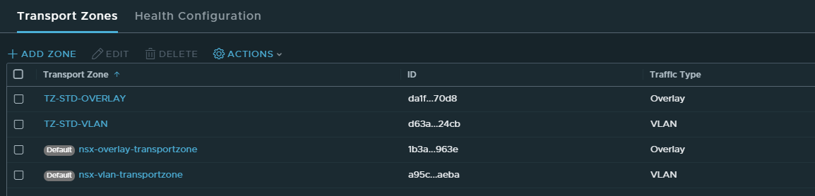
System > Fabric > Transport Zones
We need to create two transport zones:
- TZ-STD-OVERLAY
- TZ-STD-VLAN
Make sure that the traffic type is set to overlay for the overlay transport zone and VLAN for the VLAN transport zone.
System > Profiles > Uplink Profiles
Give the profile a name.
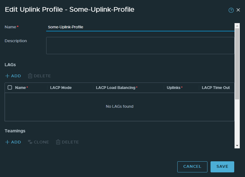
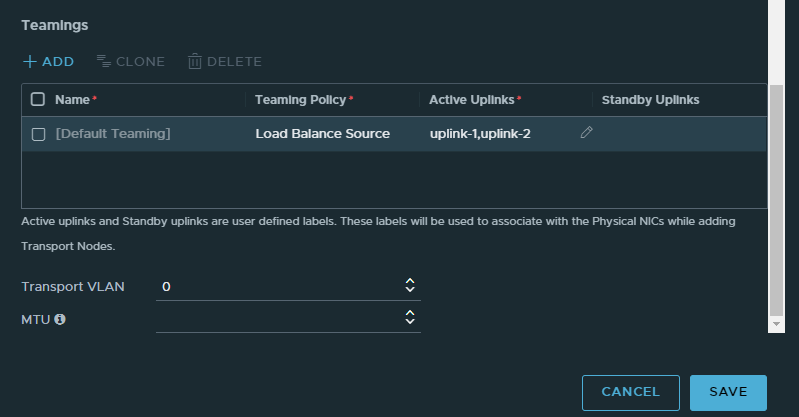
Select Load Balance Source as the policy type. Name the uplinks: uplink-1,uplink-2. No spaces. Leave the Transport VLAN as 0 because we aren’t doing VLANs.
Configuration Host Transport Nodes
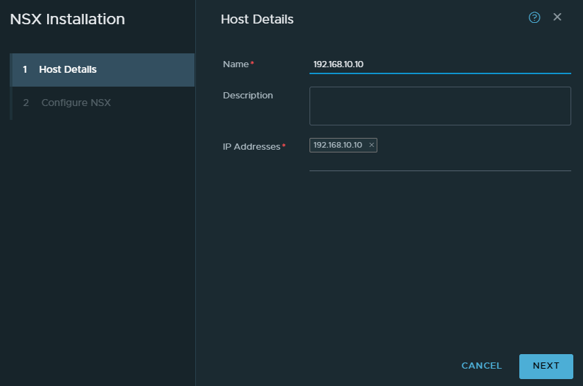
System > Fabric > Nodes > Host Transport Nodes
These will be just ESXI hosts and in our case it’s our nested ESXI host. Click configure and give it a name.
Select the “TZ-STD-OVERLAY” transport zone. Name the switch “NVDS-TZ-STD-OVERLAY” for consistency. Select the default NIOC profile and select the uplink profile we created earlier.
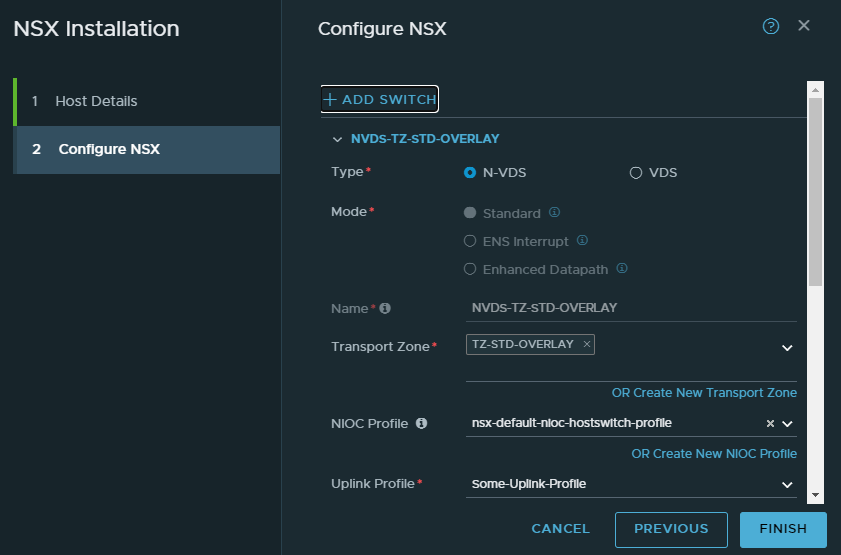
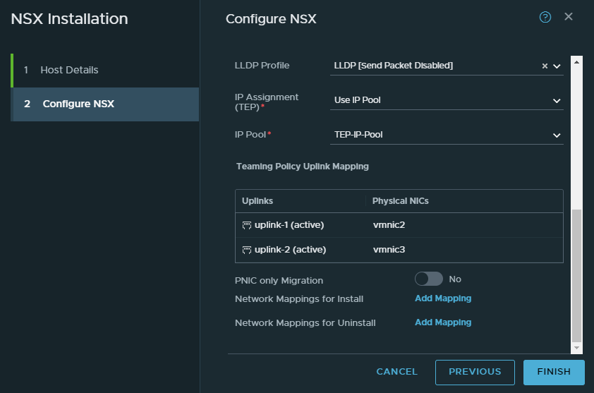
Pick the LLDP disabled profile. IP Assignment should be our IP pool we created earlier.
As for our NICs, the 3rd NIC corresponds to vmnic2 and the 4th to vmnic3. To identify this a bit easier, look at the nested ESXI hosts settings.
Physical NIC for uplink-1: vmnic2
Physical NIC for uplink-2: vmnic3
NSX Edge Node
System > Fabric > Nodes > Edge Transport Nodes
Keep in mind that NSX edge requires a cluster to be set up in vCenter. We can set up multiple NSX Edge instances split across multiple ESXI hosts for redundancy reasons. But we aren’t going to do that because it makes it more complicated.
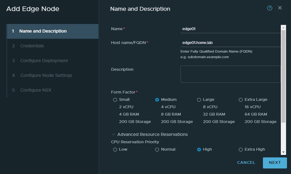
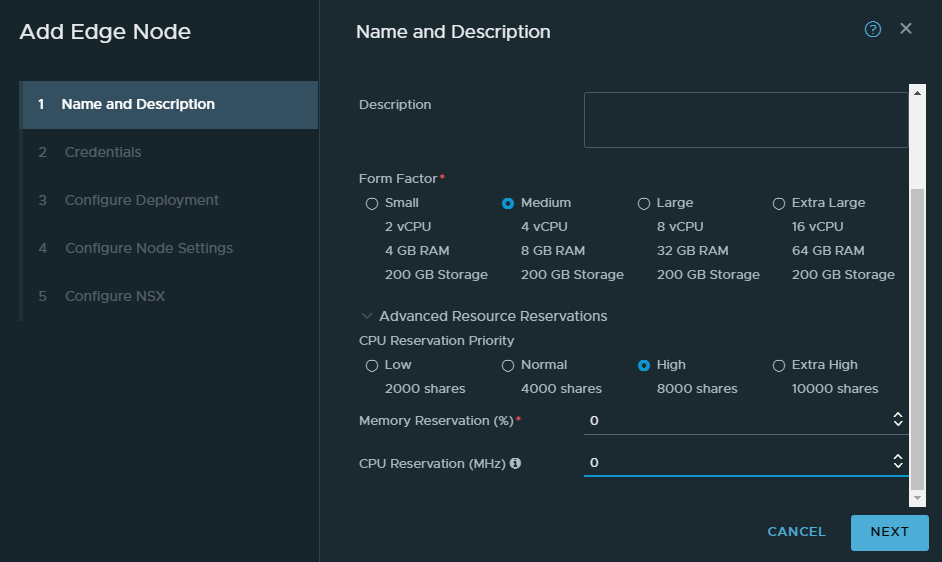
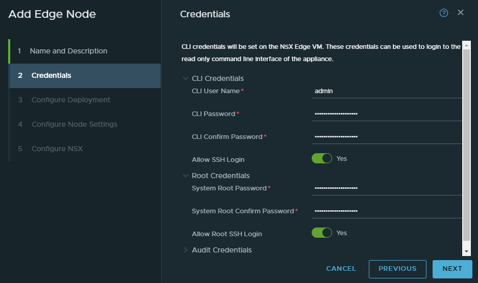
Give it a name and this will be the VM’s name. A FQDN is required hence why we have a DNS server. Keep the form factor at medium.
Again because of our scarce resources, we’ll turn off the CPU and memory reservations by entering a 0.
I wouldn’t enable SSH or root login in a production environment.
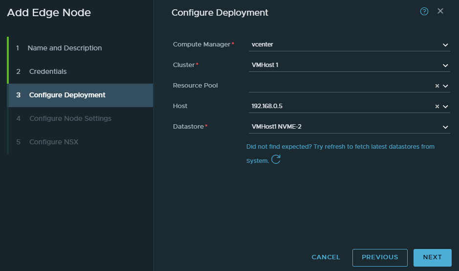
Select your compute manager. I’ve decided to install the NSX edge on my physical ESXI host.
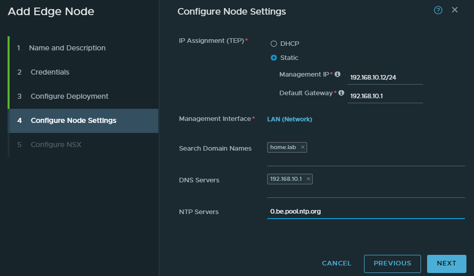
We’ll be using the “LAN” port group which has a range of 192.168.10.0/24
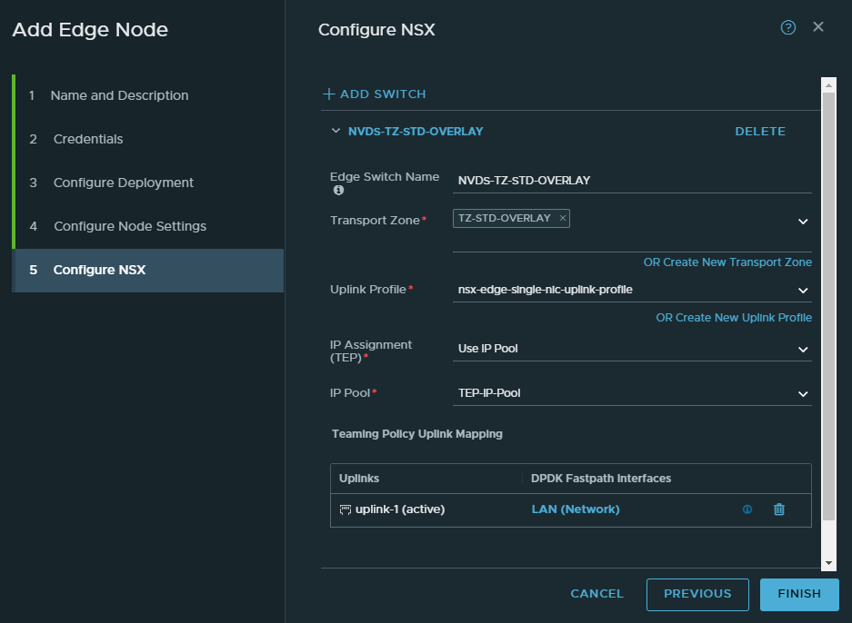
For the first switch, select the “TZ-STD-OVERLAY” transport zone. Name the switch “NVDS-TZ-STD-OVERLAY”. Select the single-nic-uplink profile. Use the IP pool we created earlier. And select the LAN port group as the uplink.
Don’t click finish yet.
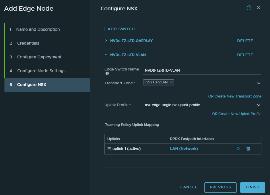
Add a new switch.
Select “TZ-STD-VLAN” as the transport zone. Name the switch “NVDS-TZ-STD-VLAN”. Select the single-nic-uplink profile. And lastly select the “LAN” port group as the uplink.
NSX Edge Cluster
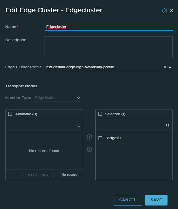
System > Fabric > Nodes > Edge Clusters
This is one of the easier steps. Basically we put all of our edge nodes in a cluster. Since we only have one, there’s not much redundancy to be found.
Tier 0 and Tier 1 gateways
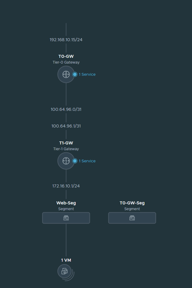
Basically Tier 0 is at the edge and is responsible for north-south traffic (or in other words LAN to WAN and vice versa). In my case, the Tier 0 gateway is directly connected with the Palo Alto firewall. 192.168.10.15 is the address the Palo Alto firewall responds to when advertising and learning routes.
Then we have our Tier 1 gateway which is basically the gateway VM’s will use. It’s primarily used for east-west traffic or in other words inter-VM traffic. But if the destination is for example the internet, the Tier 1 gateway forwards it to the Tier 0 gateway.
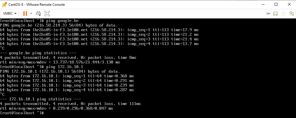
At the bottom we have our segments. VM’s behind NSX will use segments. Segments are just port groups and nothing more. They have a default gateway and so on. Currently I have a CentOS VM behind NSX and its default gateway is 172.16.10.1/24. This will make more sense as we start configuring.
Creating the T0 Gateway and configuring BGP
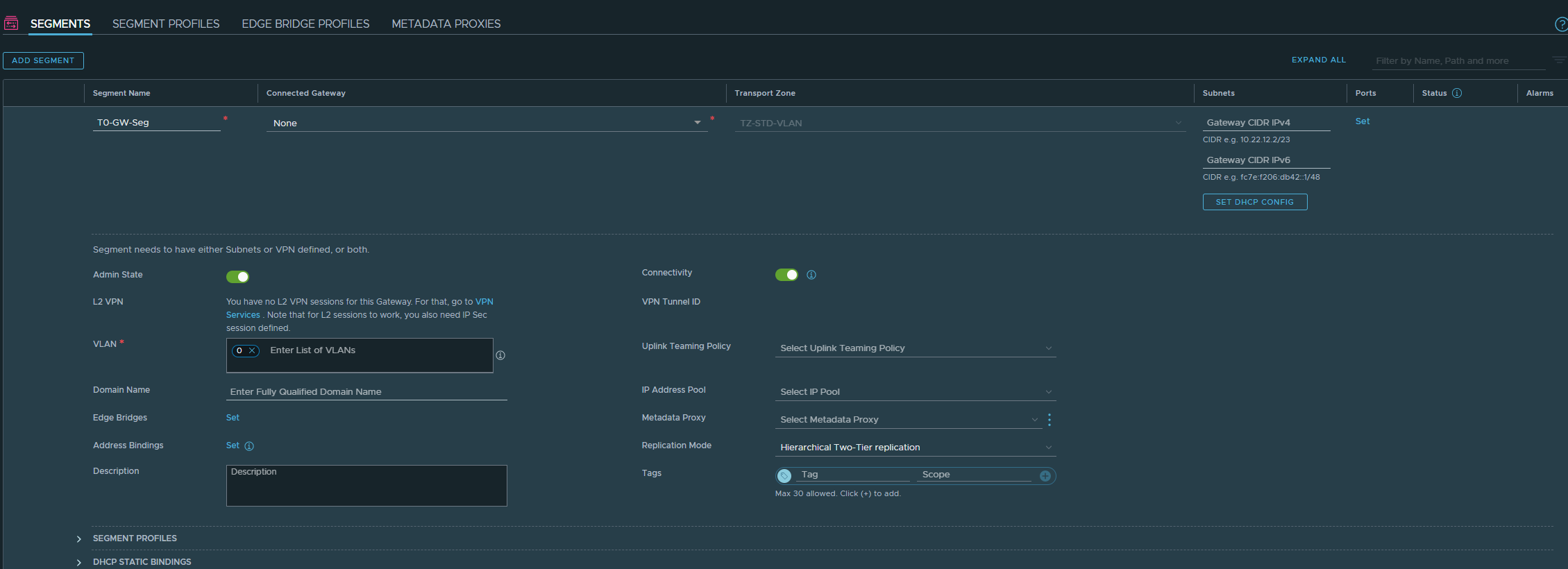
Networking > Segments
We’ll have to create a segment that belongs to the “TZ-STD-VLAN” transport zone. Give it a name. Don’t select a gateway. Select the “TZ-STD-VLAN” transport zone. Enter 0 as VLAN ID which just means that we’re not doing VLAN’s.
Networking > Tier-0 Gateways
Name it T0-GW. Select our Edge cluster we created earlier. Click save.
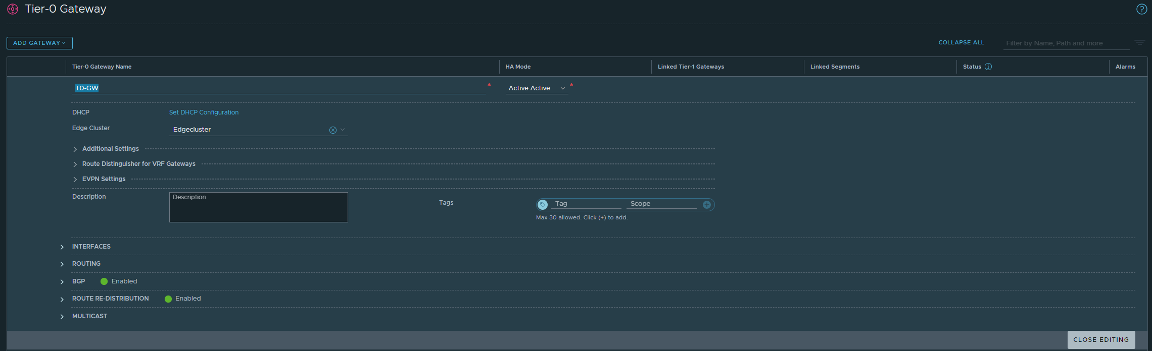
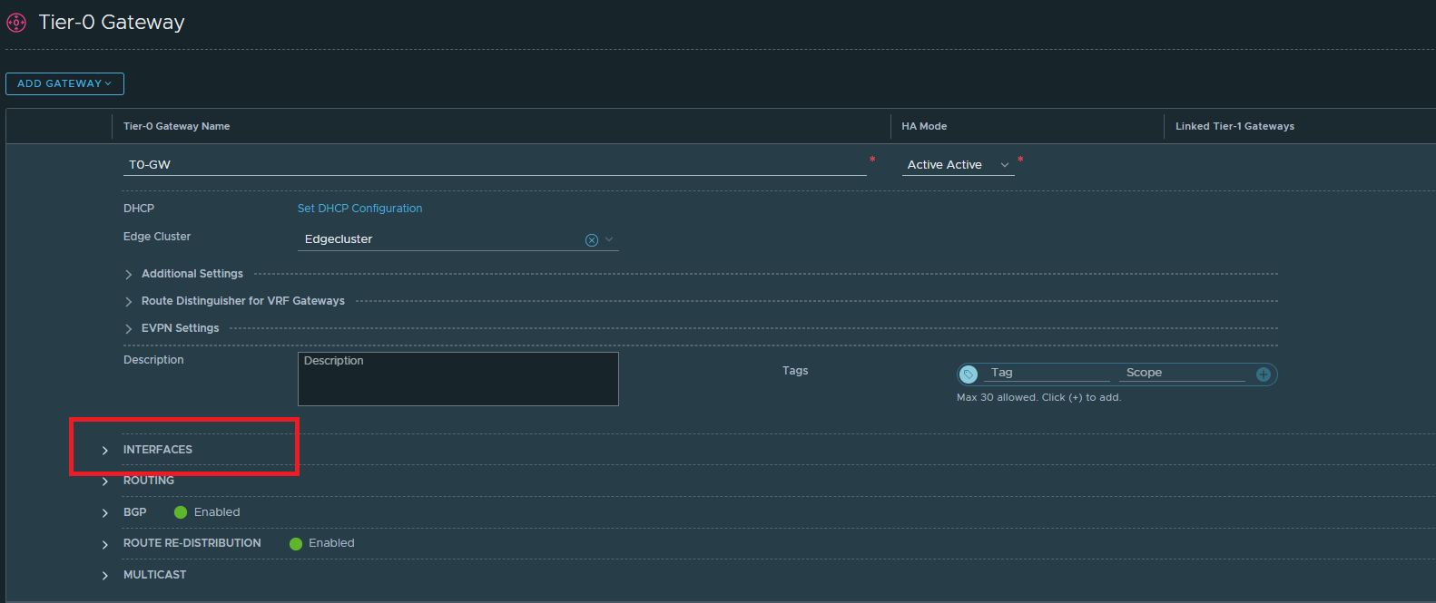
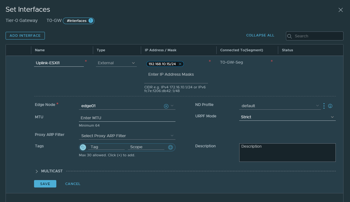
Then edit the T0-GW. Head over to interfaces to add an interface.
The IP address here should be within the same range of the LAN interface of our Palo Alto firewall (192.168.10.0/24). This address will be used for BGP advertisement to the firewall.
Then select the Edge node and save. We can’t select edge clusters here though.
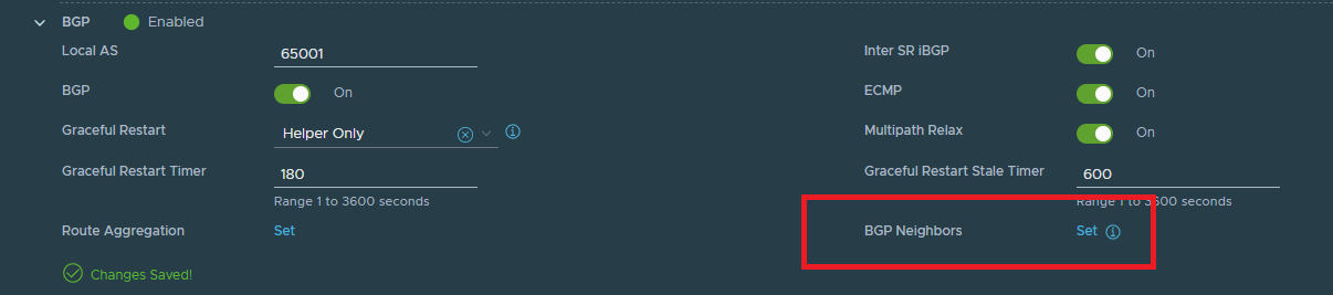
Next up we’ll configure BGP. This will advertise routes to the default gateway of the Palo Alto’s LAN interface (192.168.10.1/24).
Change the Local AS to 65001. The peer AS (Palo Alto firewall) will be 65000.

Set the BGP neighbors. I’ve already configured one, yours shouldn’t display a neighbor yet.
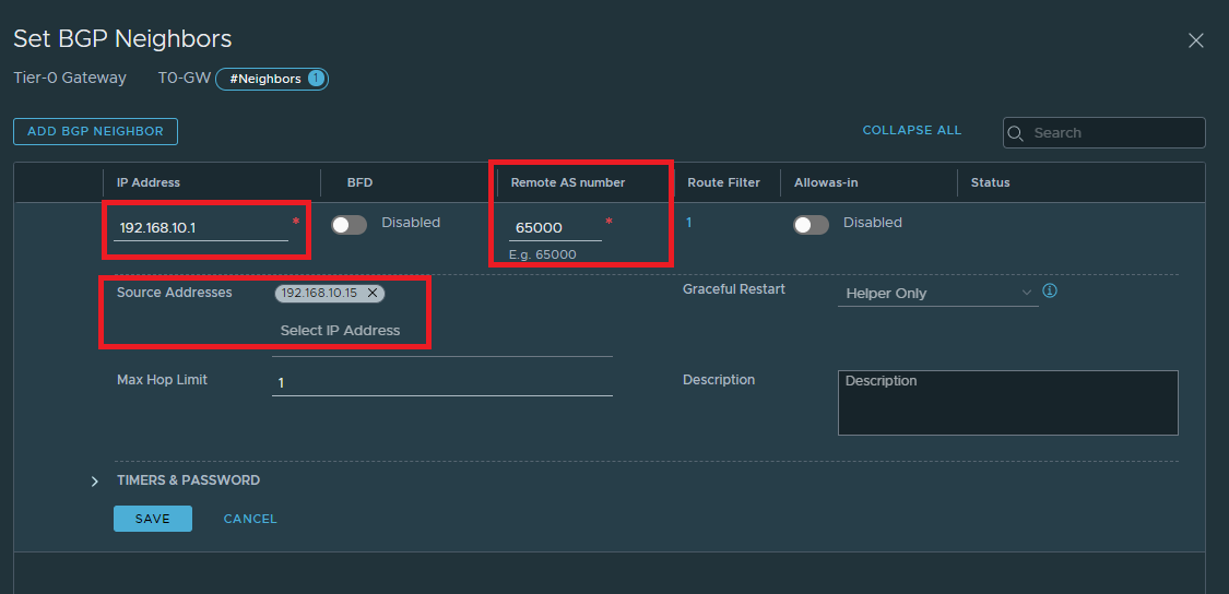
Add a BGP neighbor

The IP address here should be the default gateway of your firewall. In my case it’s 192.168.10.1/24 on the Palo Alto. The Palo Alto’s AS is 65000. The source address here should be the same as the one we’ve added to the interface here. If configured properly, the address should pop up.
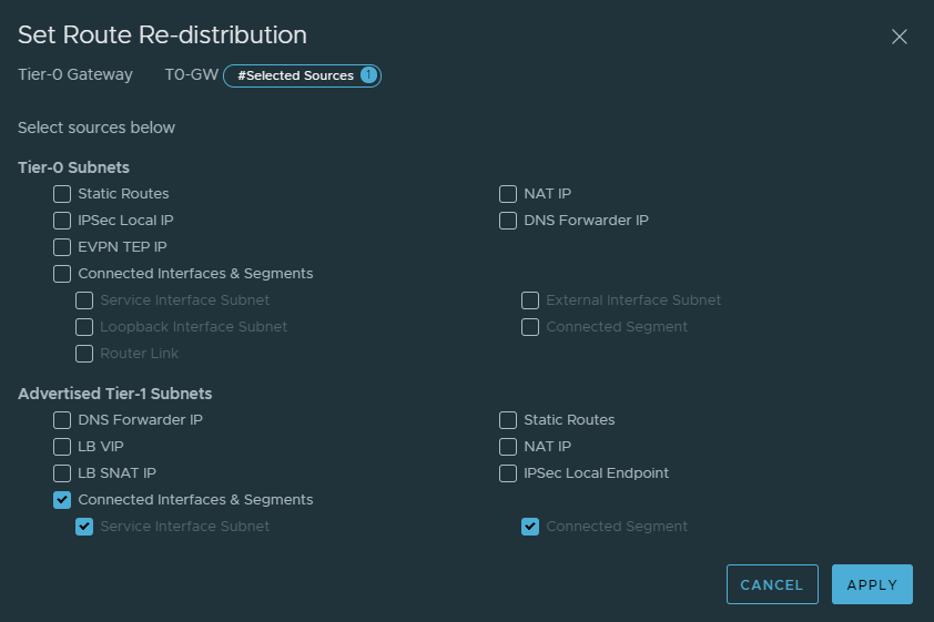
Next we want to specify the routes we want to advertise to the Palo Alto firewall. In our case we’ll advertise any routes from the T1 gateway to the Palo Alto firewall. What we mean by this is, if we add more segments to our T1 gateway – we can dynamically update it to the Palo Alto firewall.
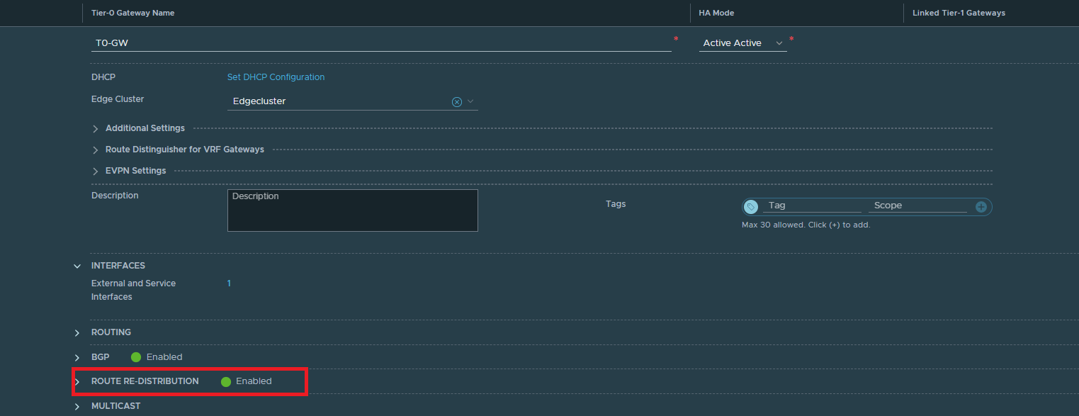
Give it a name and select the following routes.
Creating the T1 Gateway
Networking > Tier-1 Gateway
Link it to the Tier-0 Gateway and click Save.
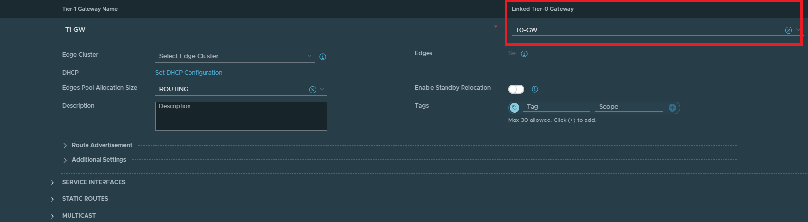
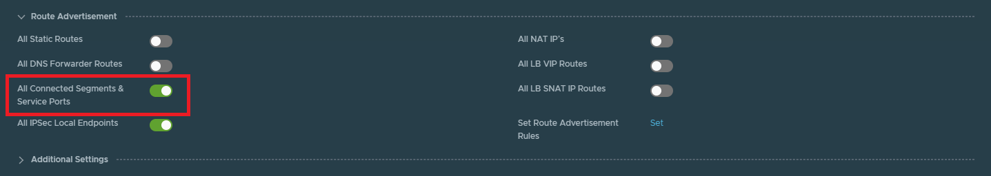
Make sure to enable “All Connected Segments & Service Ports” under the Route Advertisement tab. This will advertise any segments (e.g. 172.16.10.0/24) from the T1 to the T0 gateway.
Creating segments
Networking > Segments
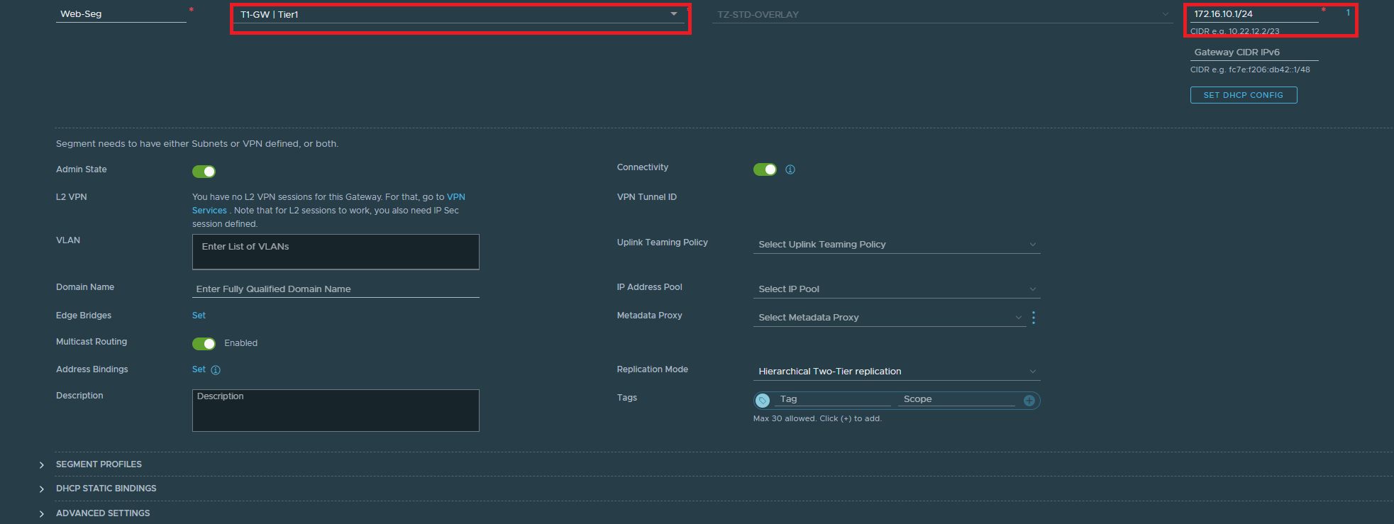
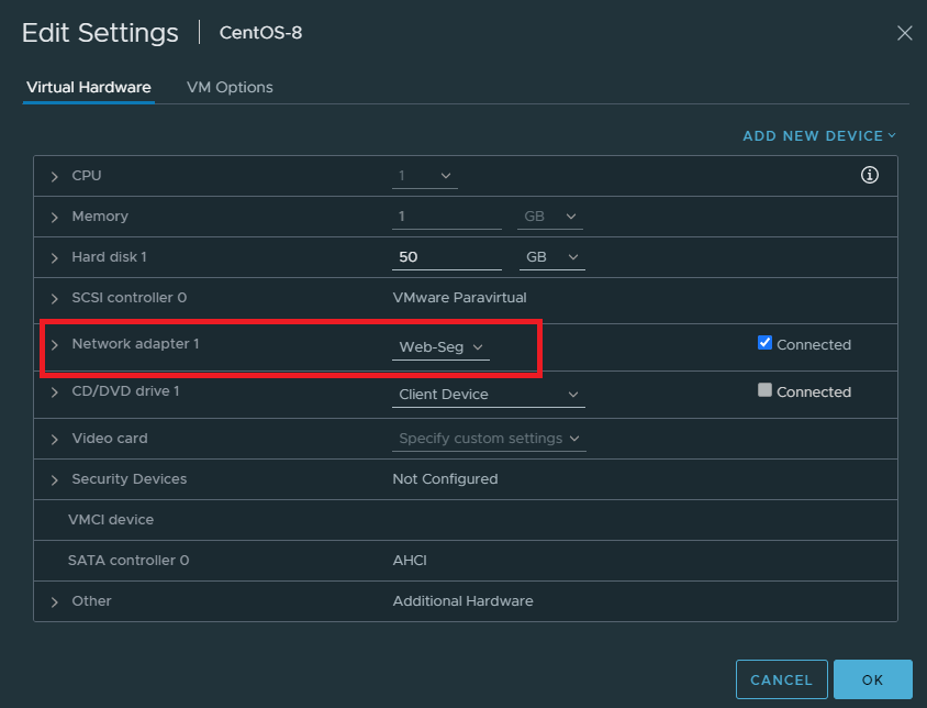
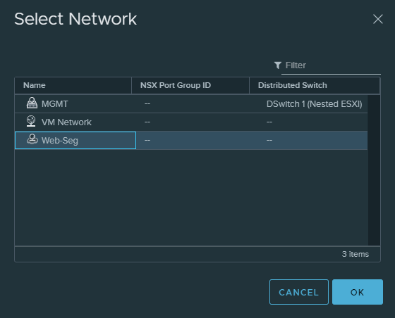
Finally, our VM’s need to have a port group to hook up with NSX. This is what segments provide. So let’s create a segment for our webservers.
Select the tier 1 gateway and enter an address as default gateway (172.16.10.1/24)
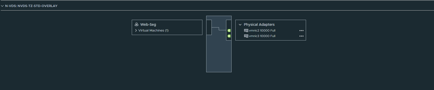
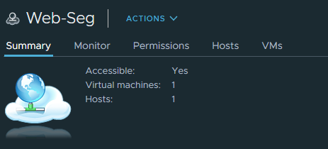
You should see that the port group was created on the nested ESXI host. It can be distinguished by its cloud icon.
Configuring BGP at the router
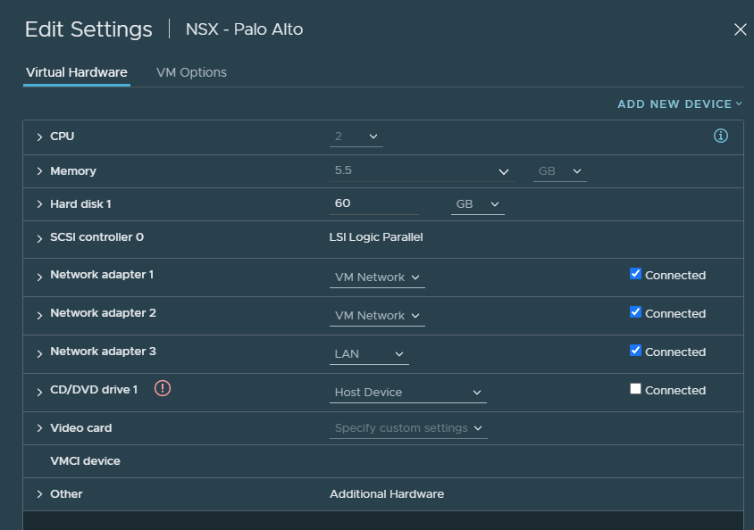
The interfaces on the PAN firewall looks like this:
- NIC#1 is the management interface
- NIC#2 is the WAN interface
- NIC#3 is the LAN interface
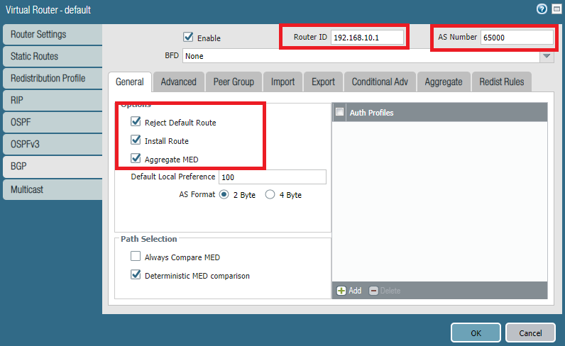
Any firewall/router with support for BGP will do the job. Palo Alto will be used for this demonstration.
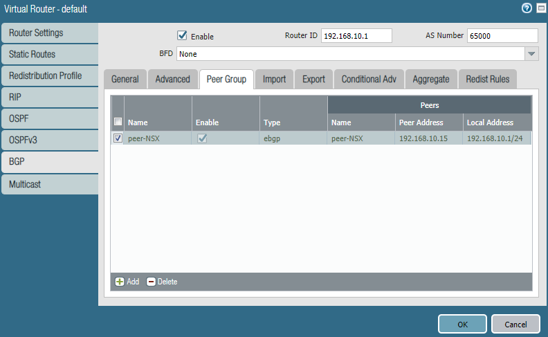
Enter the default gateway of the LAN interface as the router ID. Enter 65000 for ASN. And make sure to check the following boxes.
Under Peer Group, add a peer group and name it peer-NSX.
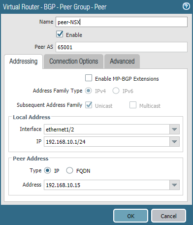
Add a peer.
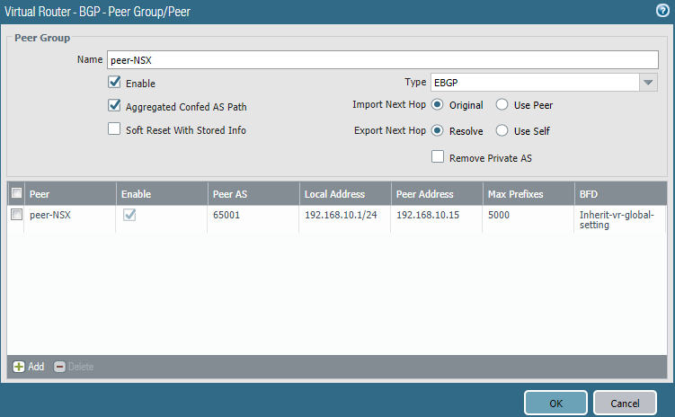
Select the LAN interface (Ethernet1/2). The Peer IP address should be the one you configured on the Tier0 gateway interface. Don’t forget to enter the correct ASN of the peer (65001 on NSX).
Under Redist Rules check the box “Allow Redistribute Default Route”. Add a rule and in addition use a redistribution profile.
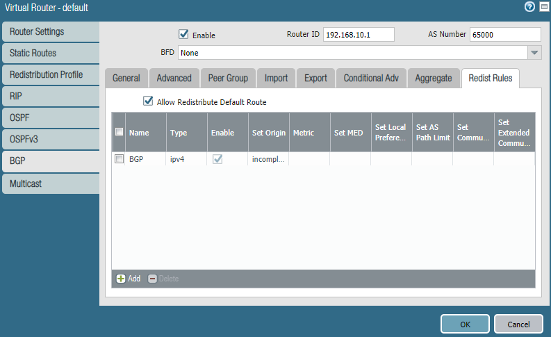
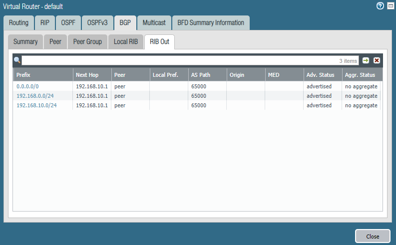
The redistribution profile looks like this. I’ve included the WAN interface (Ethernet1/1) as well, so it advertises the default-route.

Verifying BGP learned routes
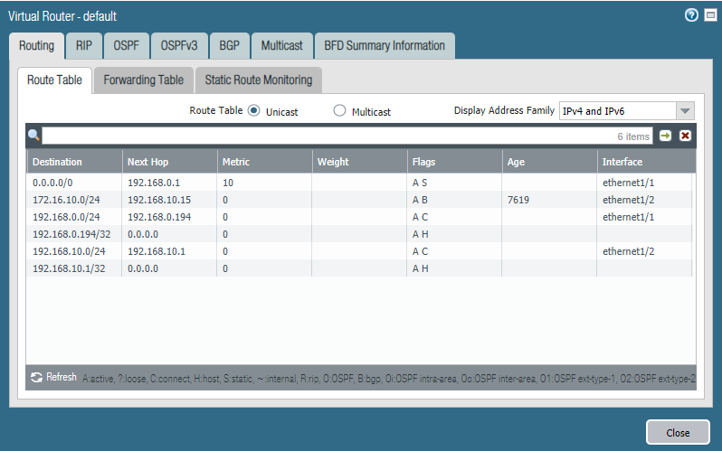
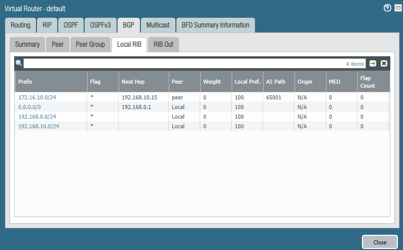
On the Palo Alto we do have a GUI. We can see 172.16.10.0/24 (Web-server Segment) is available through 192.168.10.15 (NSX).
At the NSX Edge we can also retrieve the learned routes.
edge01> get logical-router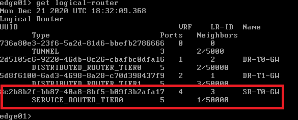
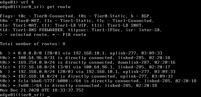
edge01> vrf 4
edge01> get route
We can see that 192.168.10.0/24 was learned and the Palo Alto firewall advertised the default route with BGP that is available through 192.168.10.1 as well.
edge01> get bgp neighbor summary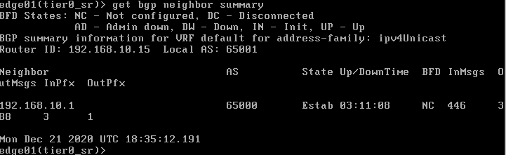
Conclusion
CentOS (Web-segment) can reach the internet.