In part 1, we’ve configured NSX Advanced Load Balancer with vCenter as the cloud platform and it’s highly recommended starting off with vCenter before attempting the NSX-T cloud. There’s so much more networking involved with NSX-T which might complicate it too much when the goal is to get familiar with NSX ALB.
The NSX-T Load Balancer has been deprecated since NSX-T version 3.2, superseded by the NSX Advanced Load Balancer which was previously branded under Avi Networks. In NSX-T version 3.2, there’s the option to deploy the ALB controller from the NSX-T Manager and it can be managed (to a certain extent) within the NSX-T Manager. However, for this guide we’ve deployed it the regular way, by using the .OVA file.
Prerequisites
- vCenter
- NSX-T Infrastructure
- 8 vCPU’s & 24 GB of RAM for the ALB Controller appliance
- NSX-ALB appliance, trial available or limited functionality for up to two Service Engines
Physical Topology
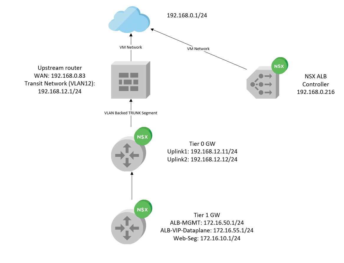
Our upstream router, with 192.168.0.83 as the WAN interface, VLAN 12 which is our transit network providing connectivity to our Edge Uplink interfaces within the 192.168.12.0/24 subnet. There’s a destination NAT policy in place, translating 192.168.0.83 -> 172.16.55.10 (VIP Address).
The NSX ALB controller is just connected to VM Network (192.168.0.0/24) which is where our vCenter and NSX-T Manager also resides at.
NSX-T Topology

In the top, we have two NSX Edge uplink interfaces (192.168.12.11/24 & 192.168.12.12/24) connecting to our upstream router/firewall. Then we have the T0 and T1 GW’s connected, with three overlay segments worth noting:
- ALB-MGMT: Service Engines will use this port group to communicate with the controller. (Subnet: 172.16.50.0/24)
- ALB-VIP-Dataplane: The segment where our VIP’s (Virtual IP Addresses) will reside on and this’ll be the dataplane that forwards traffic to our Web-Seg. (Subnet: 172.16.55.0/24)
- Web-Seg: This’ll be the segment where our web-servers will reside on. Currently, there’s just a single VM using this segment which hosts 3x instances of Nginx web-servers in Docker. (Subnet: 172.16.10.0/24)
Topology Virtual Service, VIP and pools
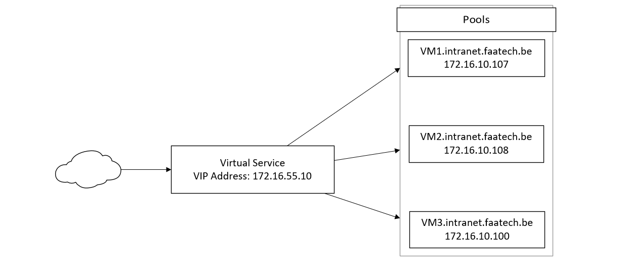
The VIP for our Virtual Service is 172.16.55.10 (ALB-VIP-Dataplane segment). And the pools will reside in the ‘Web-Seg’ segment with a subnet of 172.16.10.0/24.
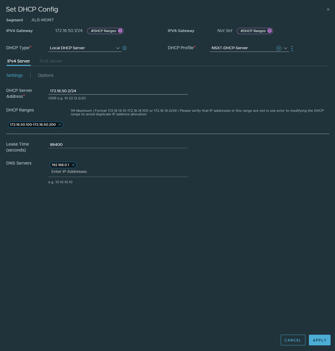
Preparing DHCP and overview segments
It’s highly recommended to enable DHCP on the MGMT, VIP and Dataplane segments to make things easier. For this demonstration a local DHCP server was used for this demonstration. The configuration is as follow:
Overview of the segments:
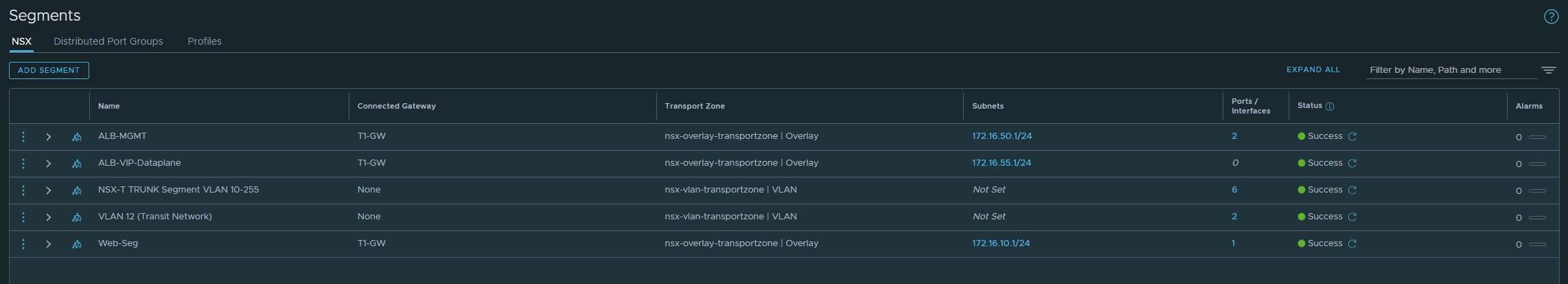
Adding the NSX-T Cloud
Infrastructure > Clouds
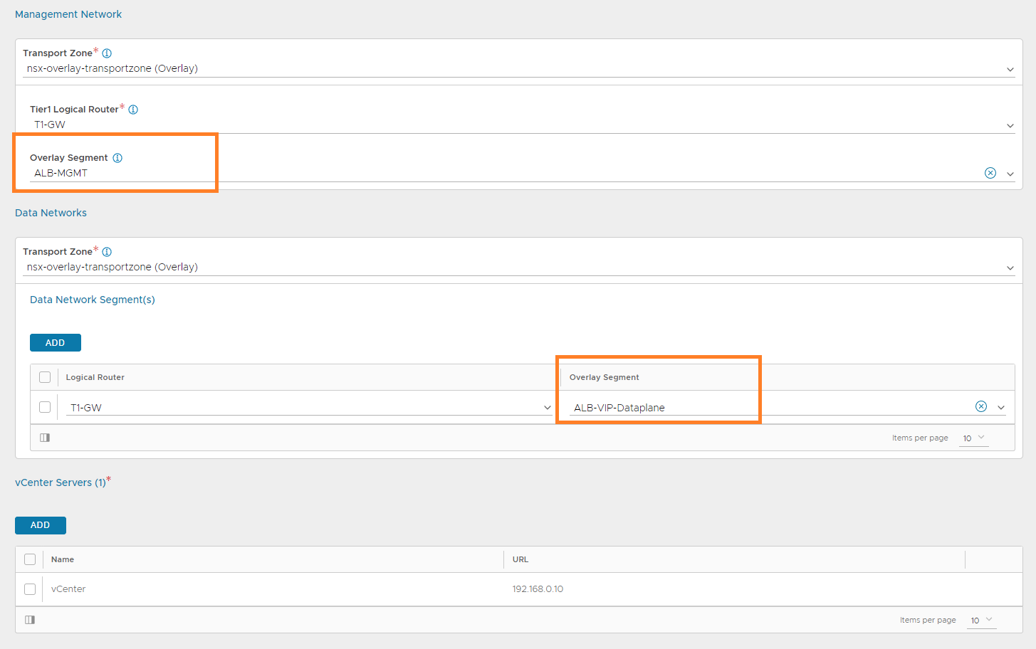
Create an NSX-T cloud. Name it, the type should already be set to NSX-T Cloud, enable DHCP, name the ‘Object Name Prefix’ and fill in the NSX-T Manager credentials/address. The Object Name Prefix is just the VM naming scheme of the SE’s. For example ‘NSXT_Avi-se-pclrq’, which can be seen in vCenter.

Next up, select the ‘ALB-MGMT’ segment for the ‘Management Network’ and select the ‘ALB-VIP-Dataplane’ Segment for the ‘Data Network’. Lastly, add the vCenter server and provide the credentials if needed.
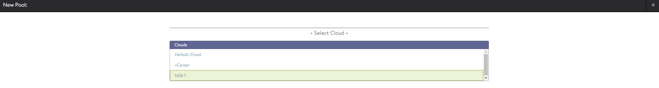
Create a pool
Applications > Pools
Create a new pool and select NSX-T as the cloud.
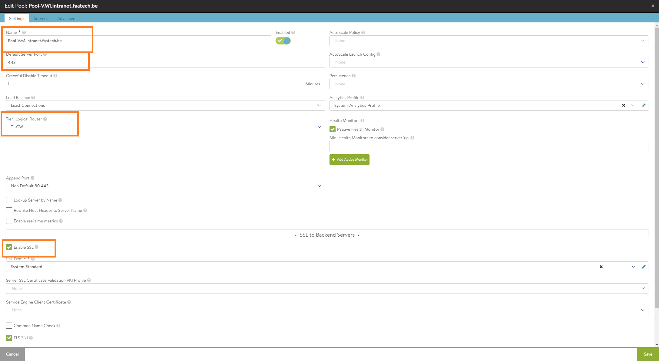
Our web-servers are listening on port 443 as well, so we’ll be opting for SSL. Keep in mind this is only for the connection between the Virtual Service and the Pool. Leaving this at port 80 is completely fine because this is strictly regarding the connectivity between the Virtual Service and the Pool (back-end servers such as Nginx web-server). The Virtual Service sets up an SSL connection with external users because the default port for a Virtual Service is 443/SSL. This is often referred by as SSL-offloading. Lastly, make sure to select the ‘Tier1 Logical Router’.
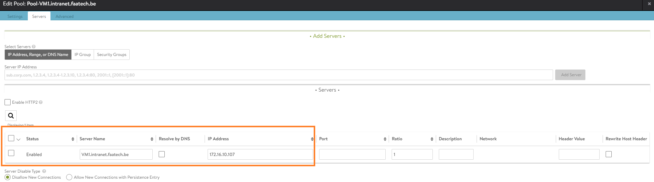
Under the ‘Servers tab, just simply enter the IP-address of the web-server. In our case, it’s 172.16.10.107 and its network segment is just ‘Web-Seg’. Alternatively, use the drop-down menu to add servers. Up to preference.

Make sure to add a name to the server, if that’s not configured yet.
No configuration will be needed in the ‘Advanced’ tab.
Repeat this step for VM2.intranet.faatech.be and VM3.intranet.faatech.be.
Creating VIP (Virtual IP Address)
Applications > VS VIPs
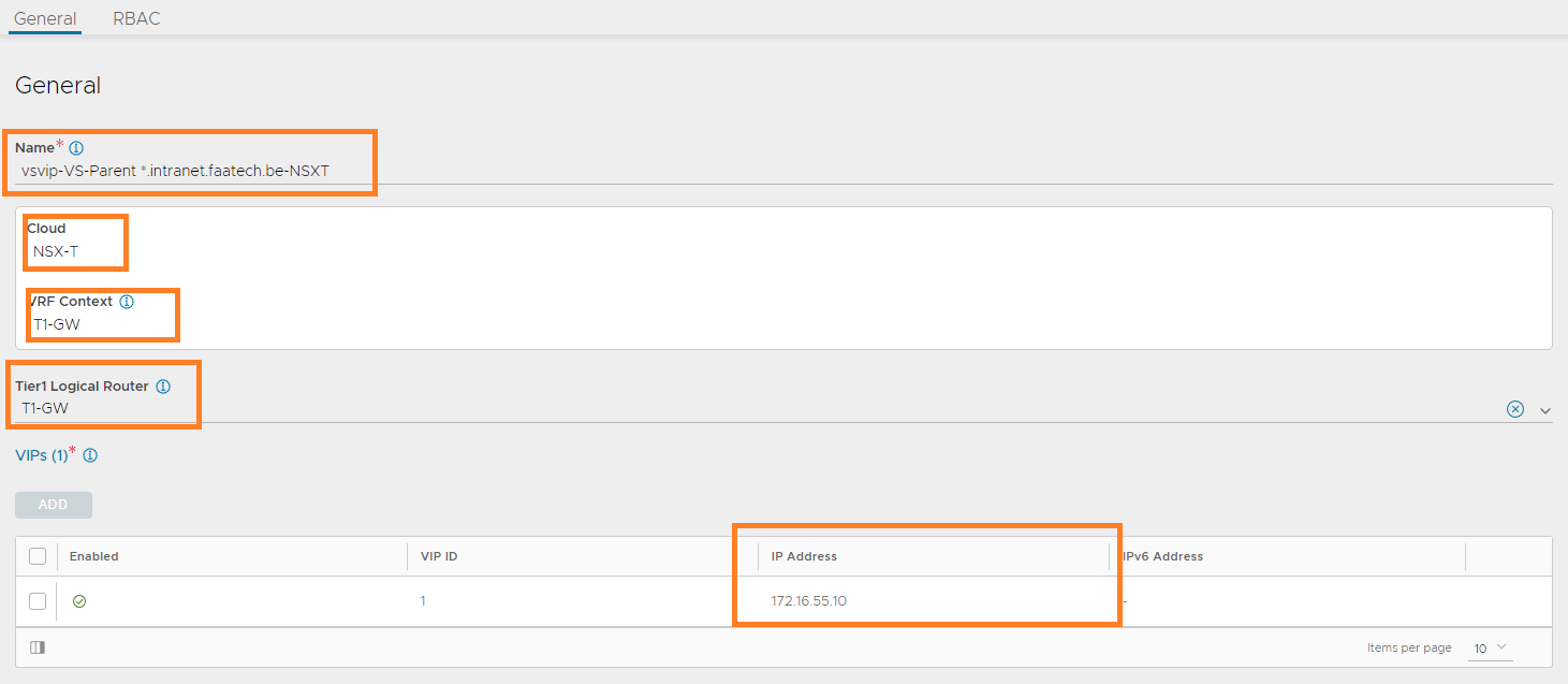
Create a new one. Name it, select the NSX-T cloud and the VRF-Context should be set to T1-GW. Select the T1 GW as the ‘Tier1 Logical Router’. Add the VIP which will be in the range of 172.16.55.0/24 (in our case, it’s 172.16.55.10).
Creating the Parent Virtual Service
Applications > Virtual Services
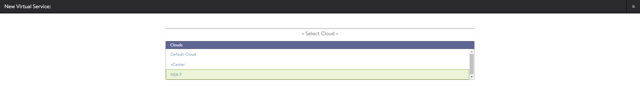
Create a new Virtual Service (Advanced Setup) and select the NSX-T cloud.
Do the following:
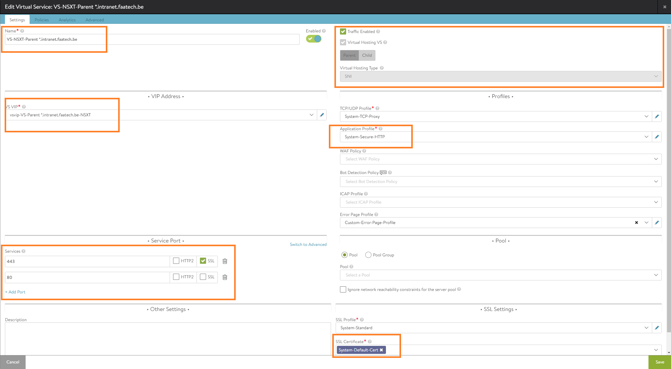
- Name the Virtual Service
- Enable Virtual Hosting VS and select ‘Parent’
- Select SNI as the type
- Select the VS VIP we created earlier for our NSX-T cloud
- Load the ‘System-Secure-HTTP’ application profile
- Add port 80 and uncheck SSL for port 80
- Load an SSL certificate
Optionally, enable logging in the analytics page. Save the configuration.
Creating the Child Virtual Service
Applications > Virtual Services
Create a new Virtual Service (Advanced Setup). Select NSX-T cloud.
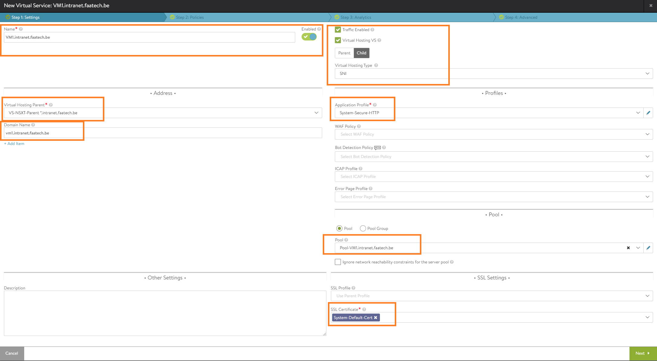
Do the following:
- Name the Virtual Service (vm1.intranet.faatech.be)
- Enable Virtual Hosting VS and select Child
- Set SNI as the type
- Select the Virtual Hosting Parent we created in an earlier step
- Set the domainname (vm1.intranet.faatech.be)
- Load the ‘System-Secure-HTTP’ application profile.
- Set the Pool (Pool-VM1.intranet.faatech.be)
- Load an SSL certificate
Optionally enable logging in the analytics tab. Then just save. And repeat this step for VM2.intranet.faatech.be and VM3.intranet.faatech.be
Managing Service Engine template configuration
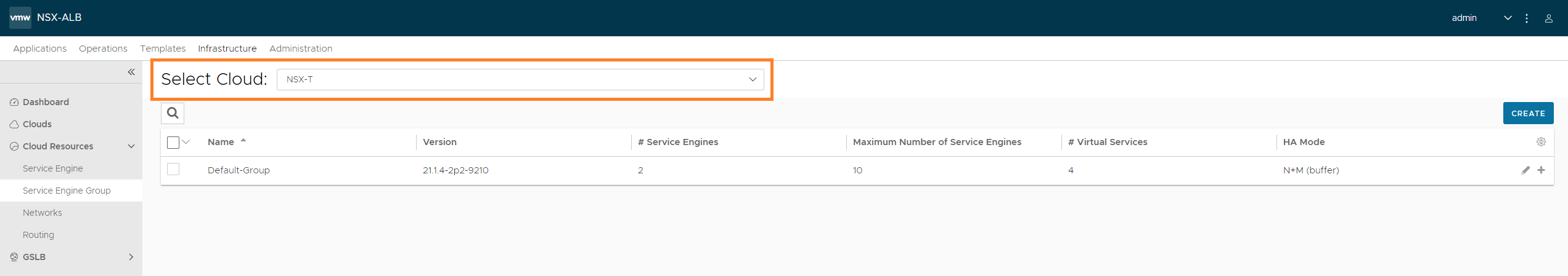
Infrastructure > Cloud Resources > Cloud Engine Groups
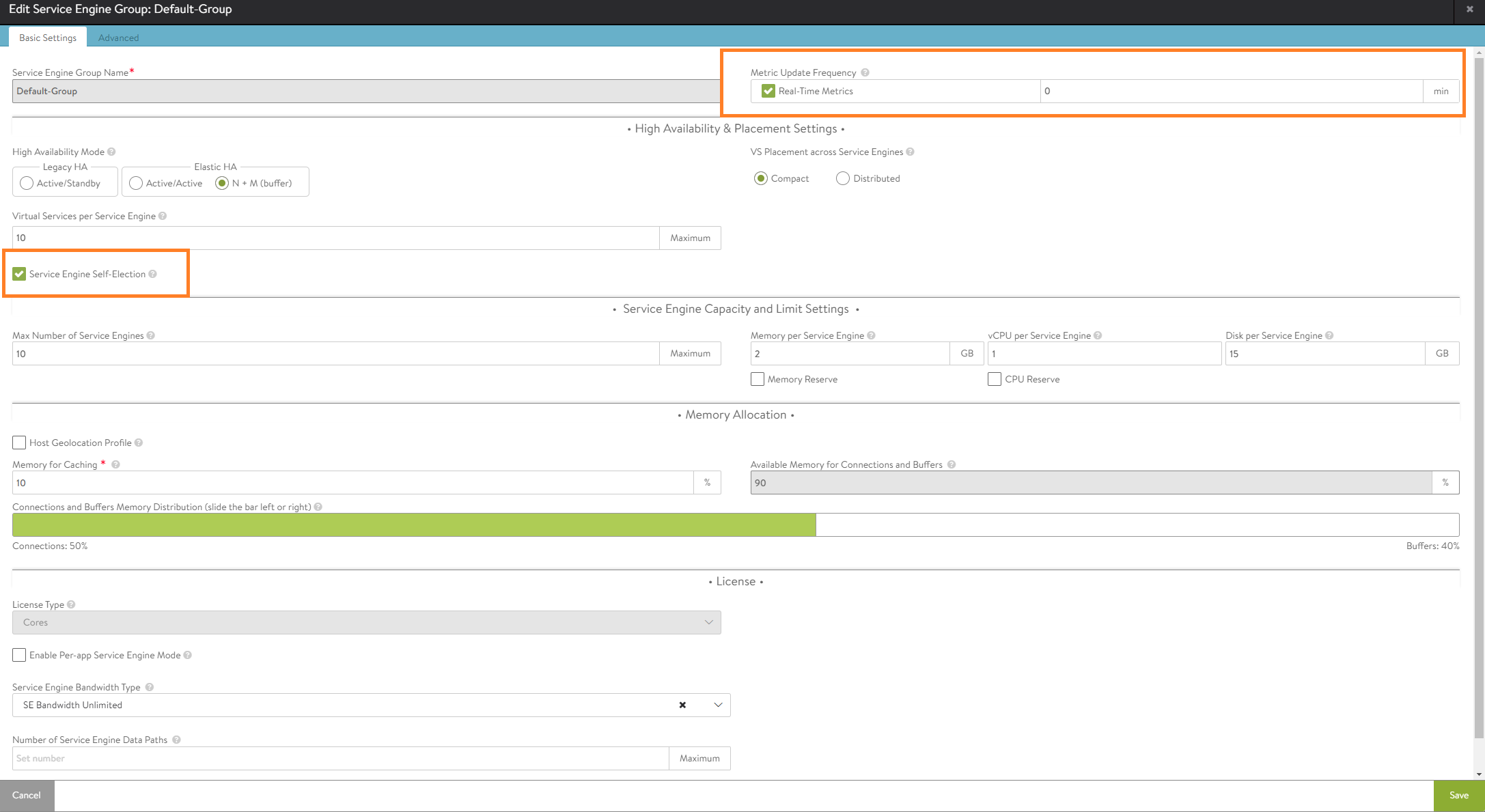
Make sure to select the NSX-T cloud. Then edit the ‘Default-Group’.
Here’s where we can change the amount of RAM, vCPU’s, HA settings etc. I’ve set the duration for logging to infinite (which is just 0 min). Also the option ‘Serivce Engine Self-Election’ has been enabled, should the controller go down.
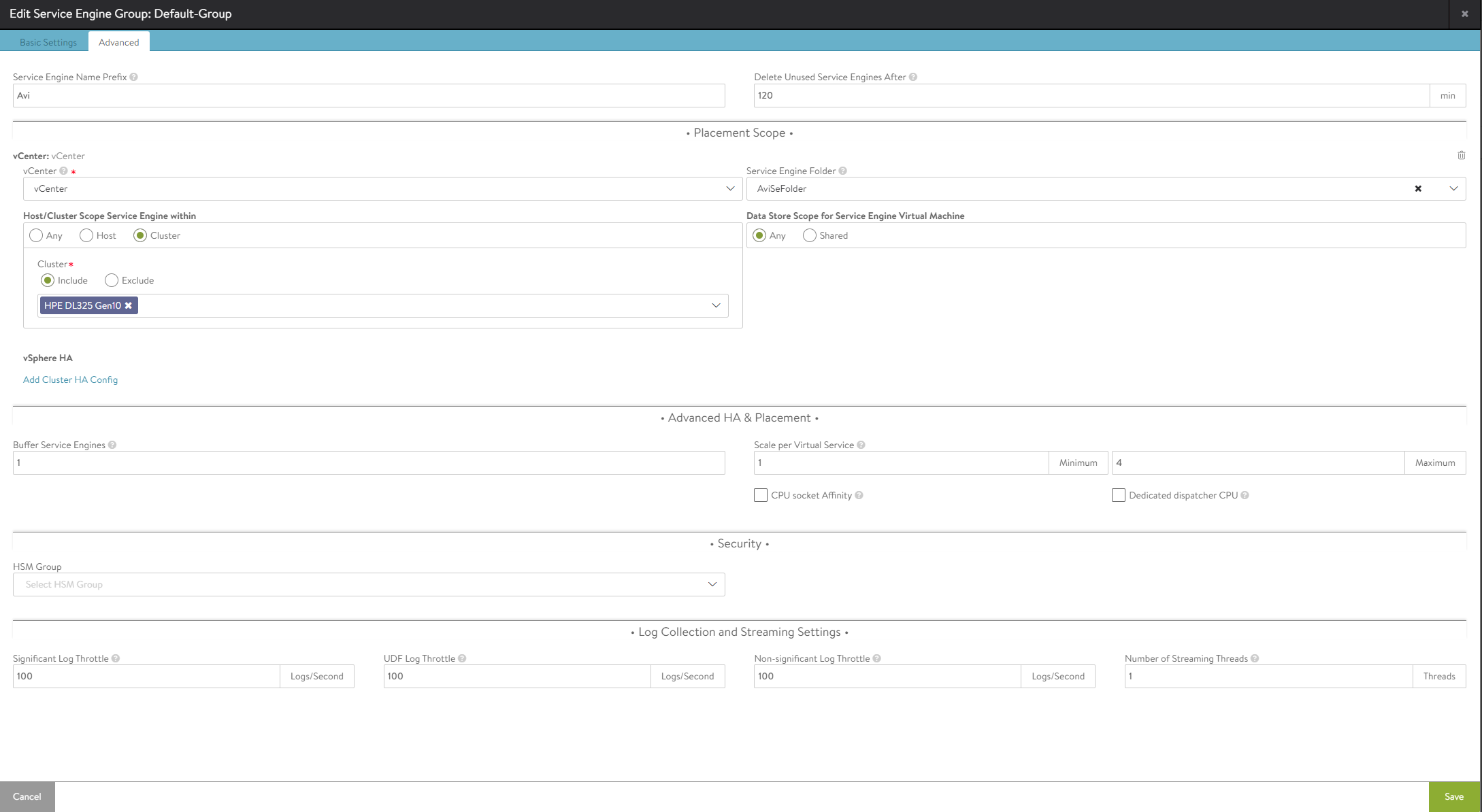
In the 2nd tab, we can select which hosts should participate and the datastores where we want to store our SE’s.
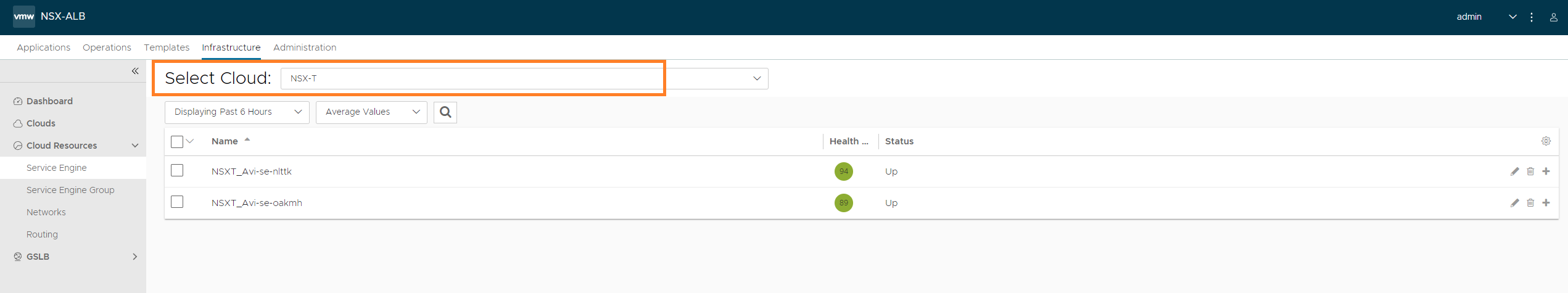
Infrastructure > Cloud Resources > Service Engine
Again make sure to select the NSX-T cloud. We should see the SE’s at this point, if not check vCenter as well.
Conclusion
Now it just comes down to testing, however it requires a DNS server with the right DNS records. A quick remedy is editing the following file ‘C:\Windows\System32\drivers\etc\hosts’. The IP address should be the one of the WAN interface of your firewall.
192.168.0.83 vm1.intranet.faatech.be
192.168.0.83 vm2.intranet.faatech.be
192.168.0.83 vm3.intranet.faatech.be
The following docker-compose.yml file was used for the back-end servers:
version: "2.1"
services:
  nginx:
    image: ghcr.io/linuxserver/nginx
    container_name: vm1
    environment:
      - PUID=1000
      - PGID=1000
      - TZ=Europe/Brussels
    volumes:
      - ./config:/config
    ports:
      - 172.16.10.107:80:80
      - 172.16.10.107:443:443
    restart: unless-stopped