In a previous guide, we’ve configured L4-TCP load-balancing in NSX-T and this time around we’ll be configuring the L7-HTTP method with SSL SNI. We’re taking advantage of making routing decisions based on L7 headers such as domain names (e.g. example.com).
For this demo, we’ll be going with the SSL-offloading method. Which just means that we’re not doing SSL between the load-balancer and the web-servers, but only on the client side.
Prerequisites
- NSX-T infrastructure
- Dynamic routing protocol such as BGP/OSPF advertising routes to the upstream router
- 3x VM’s running a web-server listening on port 80
- TLS certificate imported in NSX-T
Topology

As we can see in the north, there’s a physical firewall with a ‘public’ address of 192.168.0.83/24. Port 80 & 443/TCP will be translated to 10.40.30.50/32 which is the Load-Balancer’s Virtual IP Address. And down the south, we have three web-servers each with their own IP-address. The web-servers are connected using an overlay segment (Web-Seg).
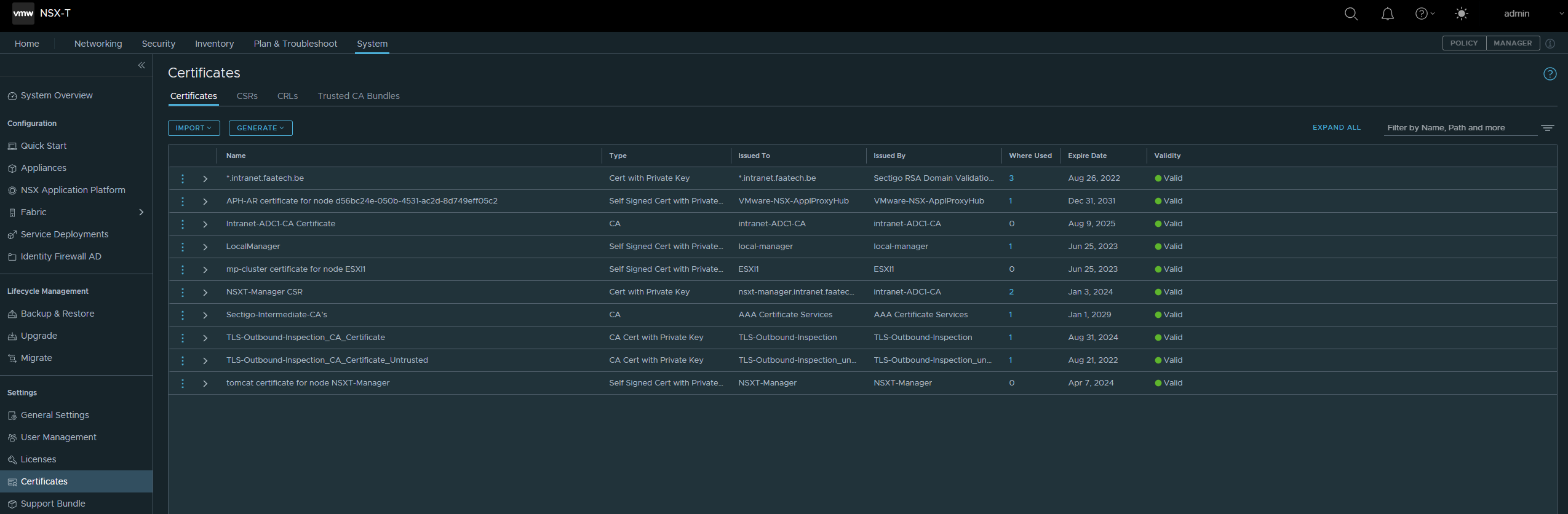
Certificates
System > Settings > Certificates
Import the web-server certificate and the root/intermediate CA’s.
Configuring route advertisement
The goal is to advertise the LB VIP address to our upstream router, considering that we’re doing NAT on the upstream router and of course there has to be a return route available for the LB VIP address. First we’ll configure the T1 to advertise the LB VIP address to the T0 gateway.
Networking > Tier-1 Gateways
Select ‘All LB VIP routes’.

Next up is the Tier 0 Gateway.
Networking > Tier-0 Gateways
Click on route-redistribution.
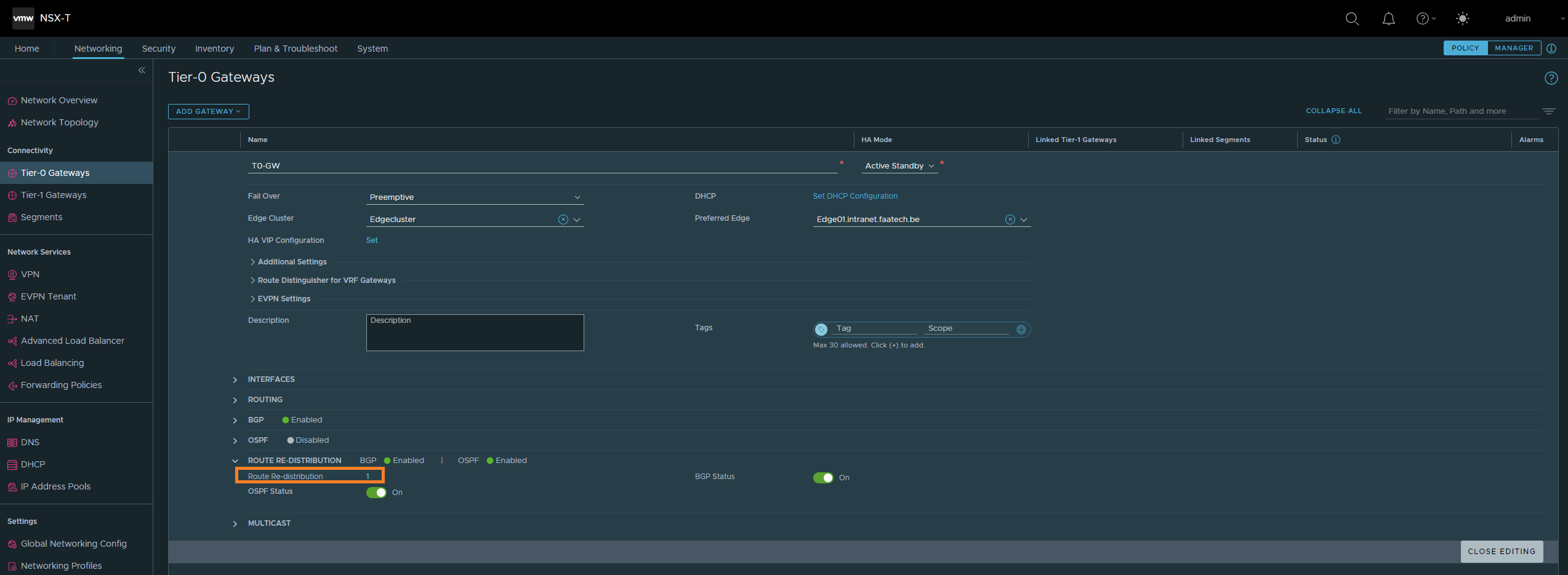
Then click on Route Re-distribution
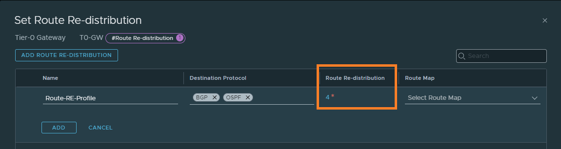
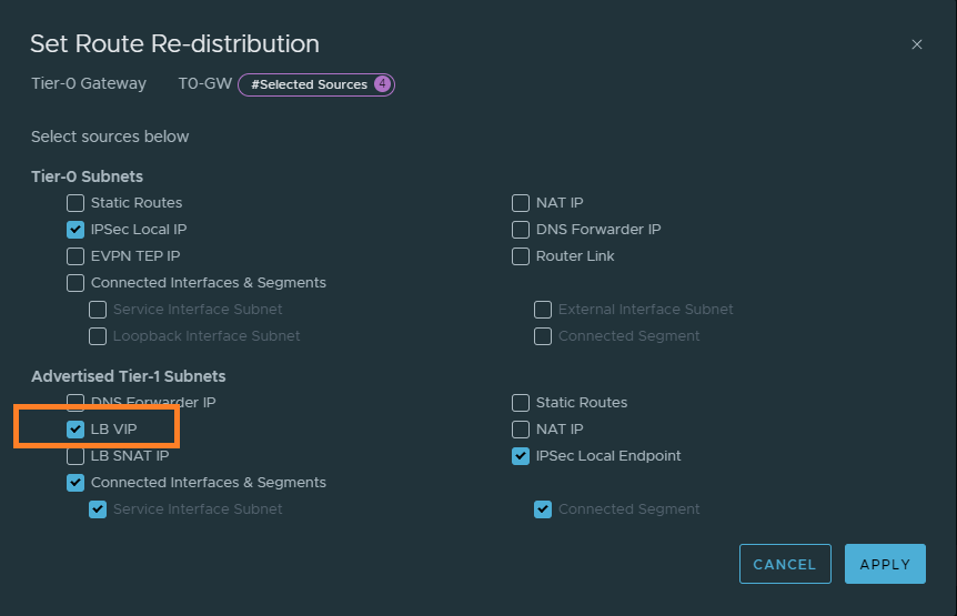
Select ‘LB VIP’. This will advertise the LB VIP address to the upstream router.
Setting up the server pools
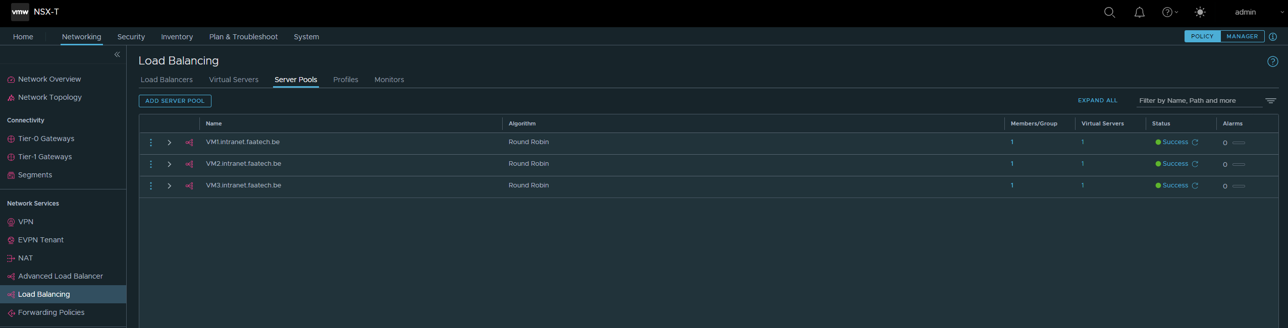
Networking > Network Services > Load Balancing > Server Pools
We don’t need the Advanced Load Balancer, which is a completely different product. Add a new server pool, like shown below. Make sure to add a Member/Group.
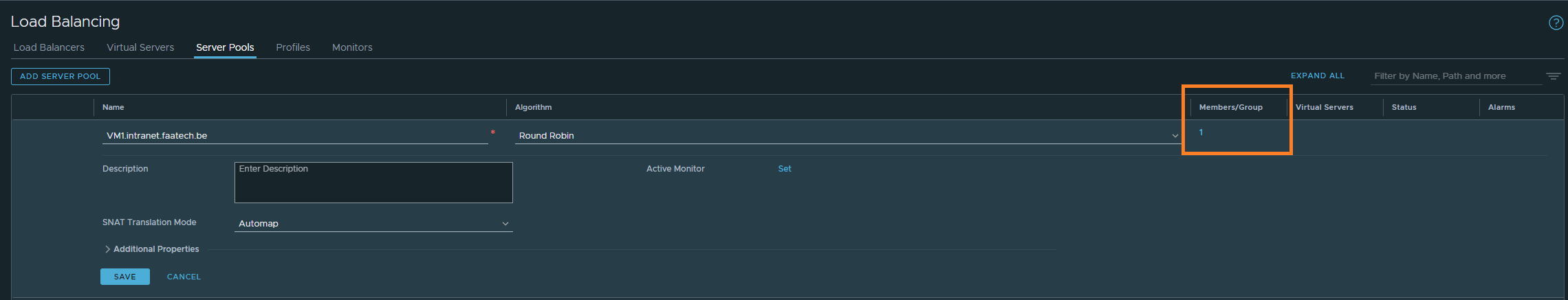
Then just either select the VM or just the IP address, in our case it’ll be the IP address. Make sure to pick port 80, because we’re not doing SSL termination between the LB and the web-servers.

Repeat the same process for VM2 and VM3.
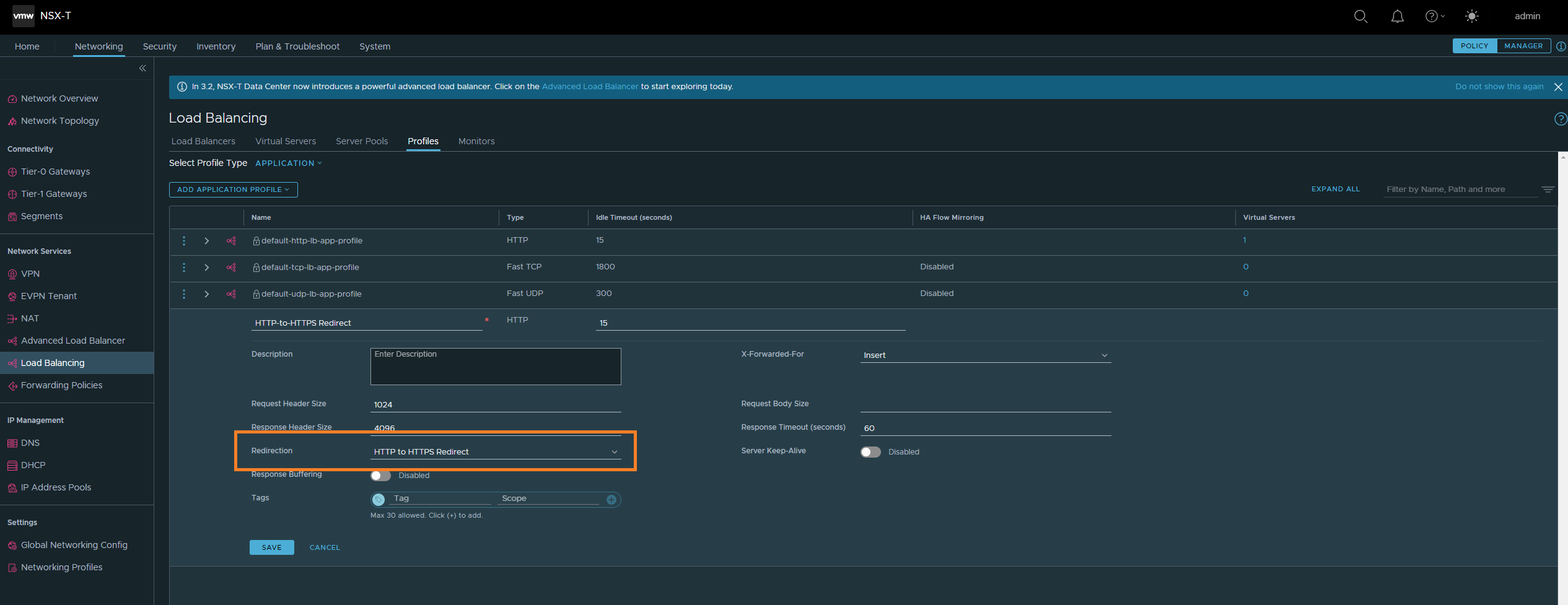
Creating HTTP to HTTPS redirect profile
This profile will be used for the service listening at port 80. The purpose of this is to redirect HTTP traffic to HTTPS.
Networking > Network Services > Load Balancing > Profiles
Then select ‘HTTP to HTTPS redirect’ for the redirect option.
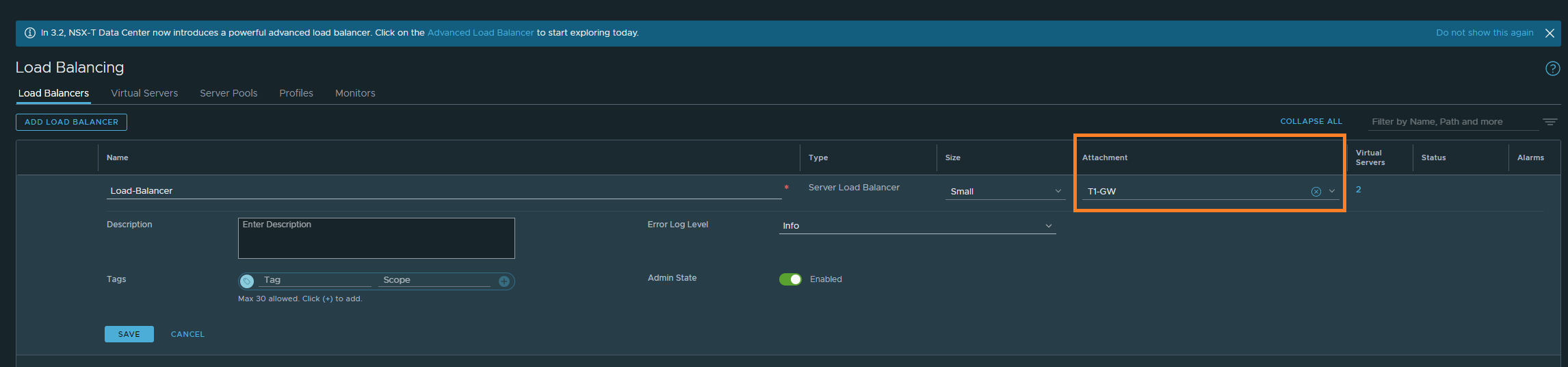
Creating the Load-Balancer
Networking > Network Services > Load Balancing > Load-Balancer
Create a new one, name it and select the T1-GW. That’s all there is to it.
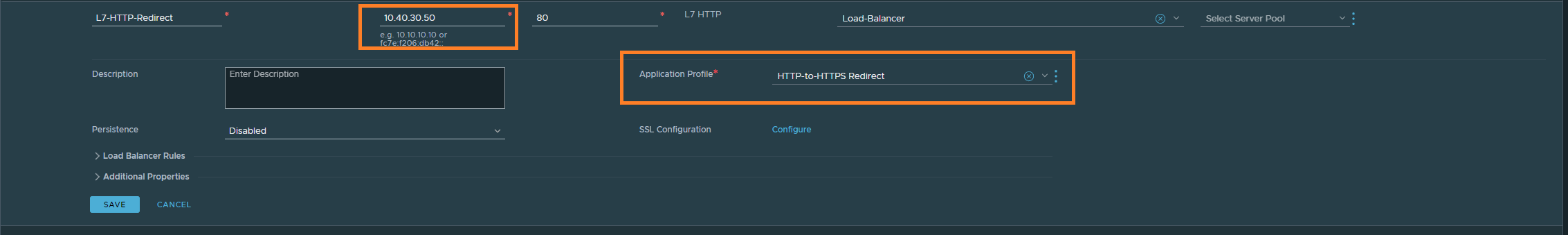
Creating the Virtual Servers
This is the part where we’ll be diving deep into SSL SNI L7 routing, setting up our SSL certificates and so on. But first things first, let’s create a Virtual Server that just listens on port 80 and load up the ‘HTTP to HTTPS redirect’ profile. The IP address here can be made up, since we’re taking advantage of dynamic routing protocols such as BGP/OSPF. Make sure that the upstream router actually translates to this LB VIP address though. Lastly, select the Load-Balancer as well that we created earlier.
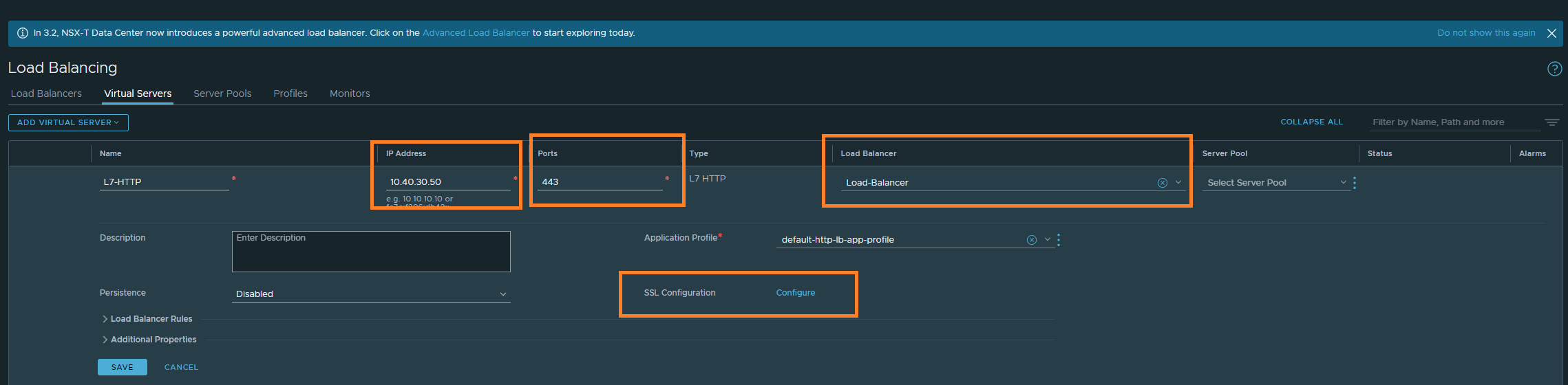
Now that we’re done redirecting HTTP to HTTPS, we may dive into SSL SNI. First, create a new L7 HTTP. Enter the same LB VIP address, port 443 and select the Load-Balancer we created earlier. Once that’s done, we’ll be configuring SSL in the next step.
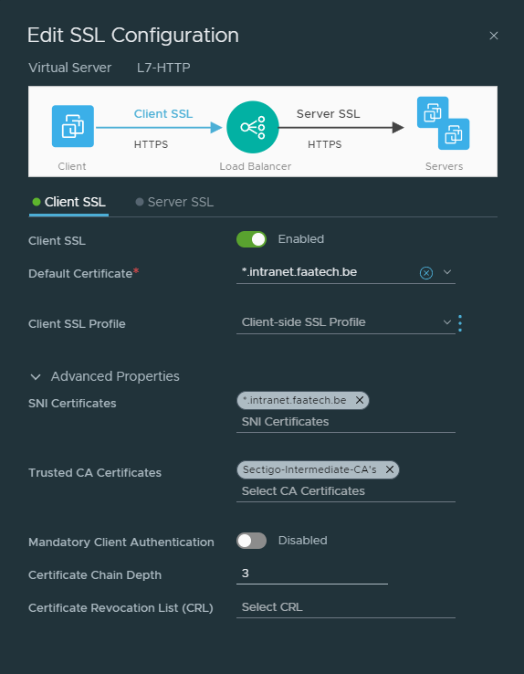
Click on ‘Configure’ under SSL Configuration. Because we’re only doing SSL offloading, we won’t be configuring ‘Server SSL’, that’s between the LB and the web-servers. Select the certificate, then under advanced the SNI certificate which should be the same as the default certificate. Then load the intermediate/root CA’s. And that’s about it.
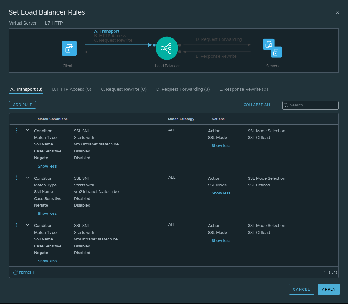
Creating the transport rules
First, let’s configure a transport rule which will be on the side between the client and the Load-Balancer.
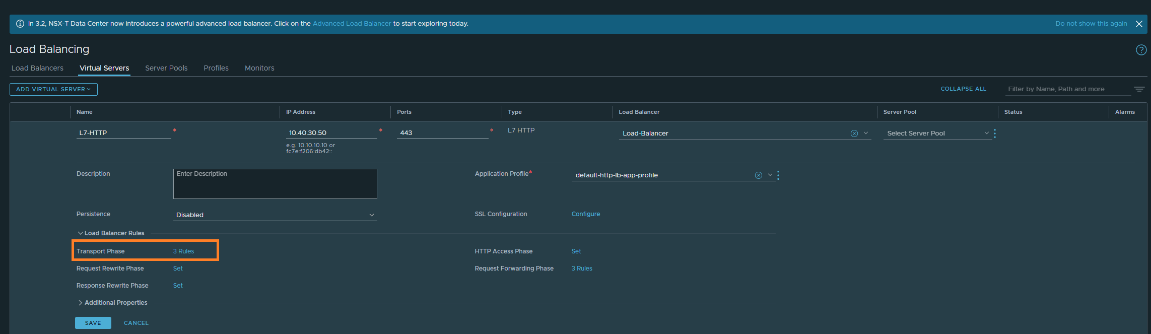
Then configure the rules as shown below:
Then head over to ‘Request Forwarding’. Configure the rules as shown below.
The mapping is quite simple:
VM1.intranet.faatech.be -> 172.16.10.107
VM2.intranet.faatech.be -> 172.16.10.108
VM3.intranet.faatech.be -> 172.16.10.109

Conclusion
Now it’s just a matter of testing it out. We’ll be needing DNS records either on the localhost or by using a DNS server. Editing the host file may be the quickest to do and that happens to be so in our case.
192.168.0.83 vm1.intranet.faatech.be
192.168.0.83 vm2.intranet.faatech.be
192.168.0.83 vm3.intranet.faatech.be