This is the 3rd part of this series. Click here for the 2nd part.
Topology overview
Carefully analyze the topology before you begin.
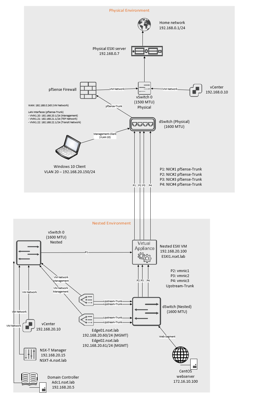
The IP blocks that are used are as follow:
| Network | VLAN ID | Subnet |
| Management Network | 20 | 192.168.20.0/24 |
| TEP Network | 21 | 192.168.21.0/24 |
| Transit Network | 22 | 192.168.22.0/24 |
The interfaces on the pfsense router:
| Interface name | VLAN ID | Address | MTU |
| vmx0 (WAN) | No VLAN | 192.168.0.245/24 | 1500 MTU |
| vmx1 | No VLAN | No IP address | 1600 MTU |
| vmx1.20 – Management Network | 20 | 192.168.20.1/24 | 1600 MTU |
| vmx1.21 – TEP Network | 21 | 192.168.21.1/24 | 1600 MTU |
| vmx1.22 – Transit Network | 22 | 192.168.22.1/24 | 1600 MTU |
Interfaces and switch configuration inside the nested environment:
| Uplink# | NIC# | Switch-type | Location |
| Uplink-1 | vmnic0 | vSwitch0 | Inside nested environment |
| Uplink-2 | vmnic1 | dSwitch | Inside nested environment |
| Uplink-3 | vmnic2 | dSwitch | Inside nested environment |
| Uplink-4 | vmnic3 | dSwitch | Inside nested environment |
Creating an uplink profile and configuring Transport-Nodes
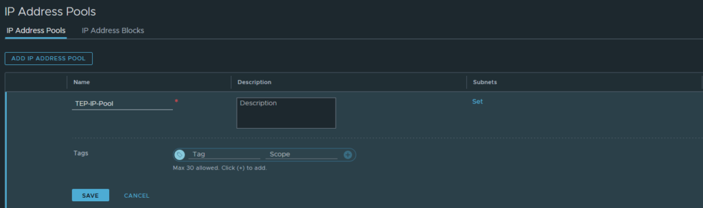
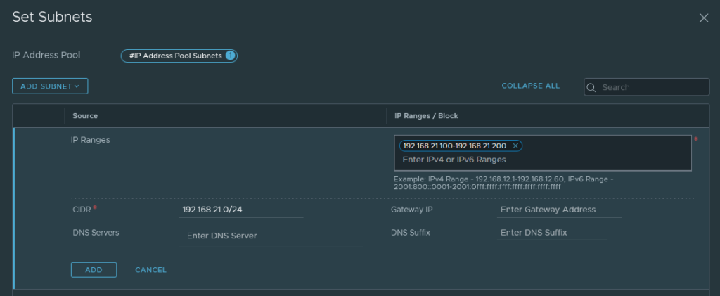
Let’s begin by creating the TEP IP Pool.
Networking > IP Management > IP Address Pools
Add a new IP-Pool.
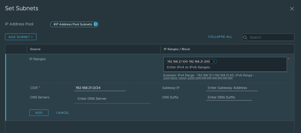
Then click ‘subnets’ to add a range of IP addresses. It has to be within range of the TEP Network (VLAN 21 – 192.168.21.0/24). There’s no need to add a default-gateway because they’re all in the same L2 zone, but you may do so if you wish.
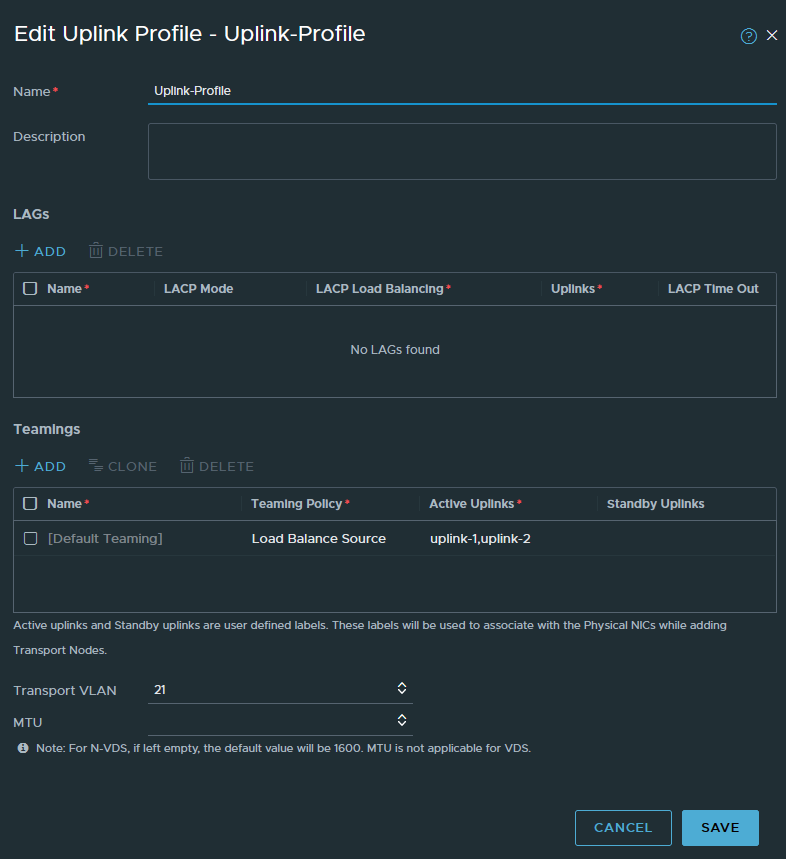
System > Fabric > Profiles > Uplink Profiles
We have to create a new uplink profile which will be used for our Transport-nodes and Edge nodes. Transport nodes are just ESXI hosts. Edges are just an on & off ramp e.g. for external connectivity.
Select ‘Load Balance Source’ as the teaming policy. Name the active uplinks however you wish, it does not matter because it’s just a naming scheme after all. The VLAN ID has to be 21 because that’s the VLAN of our TEP Network.
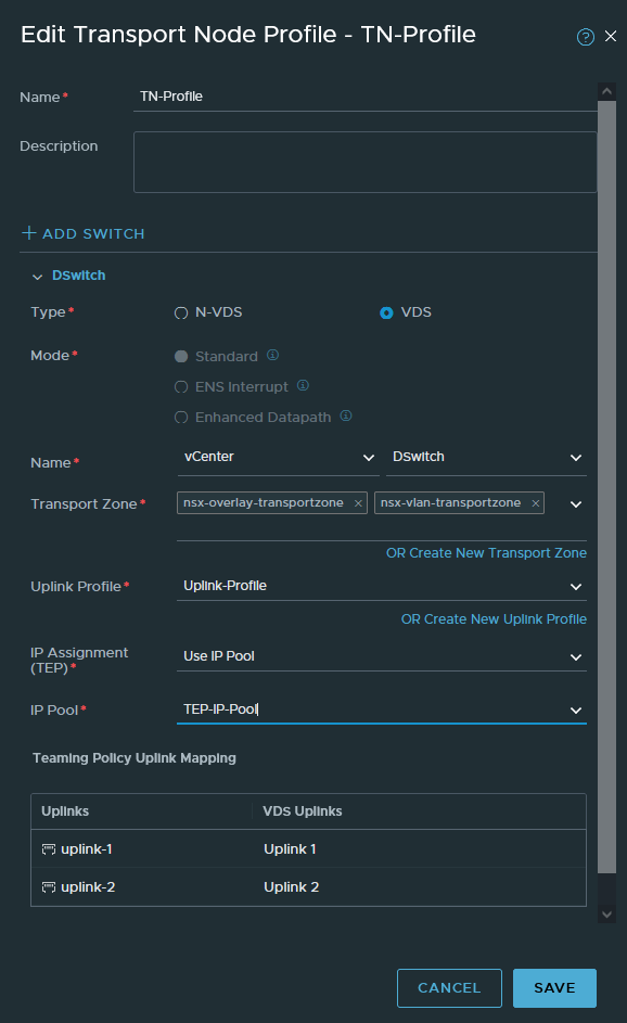
System > Fabric > Profiles > Transport Node Profiles
We’ll create a TN-profile so that we can attach it to a cluster. The advantage to this method is that whenever we add more ESXI hosts to a cluster, they’ll be automatically configured with the same profile and settings.
We have two options; N-VDS or VDS. N-VDS reserves physical interfaces and we cannot use these interfaces for anything else. The switch won’t be visible in vCenter either. The other option is VDS, which is just a dSwitch so we can just use the dSwitch that we created in part 2 of this series. We’ll be going with VDS.
Select the ‘nsx-overlay-transportzone’ and ‘nsx-vlan-transportzone’. The overlay transport zone is mandatory. If we want to do VLAN backed segments, then we have to include the VLAN transport zone for our Transport-Node. The benefit of VLAN backed segments is useful to directly connect a VM to the physical router, so we don’t have to deal with the T0 and T1 routing etc. However, the VLAN transport zone is not mandatory. But it is required on ESXI servers that host the Edge VM, so that we have inter-TEP communication between them.
Select the IP pool we created earlier (192.168.21.100-192.168.21.200 range).
Select the uplink profile we created and then choose the dSwitch (VDS) uplinks that you want to use. We’ve got 3 uplinks on our dSwitch, so we’ll only get to see uplink-1 (vmnic1), uplink-2 (vmnic2) and uplink-3 (vmnic3).
You can create an IP pool under Networking > IP Management > IP Address Pools
Once that’s done, we can assign the Transport-Node profile to the cluster. This will essentially prepare the ESXI host for NSX-T. Make sure to do this on the cluster level and not per host.
System > Fabric > Nodes > Host Transport Nodes
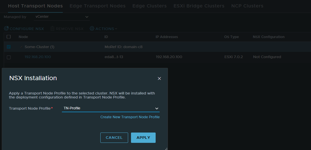
Once it’s complete, it should show that it was successful and the TEP addresses.

Installing Edge Transport nodes
First we have to create a new VLAN-backed segment that will tag from 0-4094. This segment will be used as the uplink port group when we’re configuring NSX Edge. Name it ‘Upstream-Trunk’, select the ‘nsx-vlan-transportzone’ and enter a range of 0-4094 in the VLAN field. Click save.

We will be deploying two Edge nodes and putting them in a cluster. Edge nodes are essentially just VM’s that reside on an ESXI host. You can also move them around if you wish to do so. Edge nodes will be a part of our TEP Network (VLAN 21) as well, they’ll be connected to our Transit Network (VLAN 22) for external connectivity such as the internet.
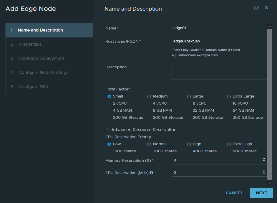
System > Fabric > Nodes > Edge Transport Nodes
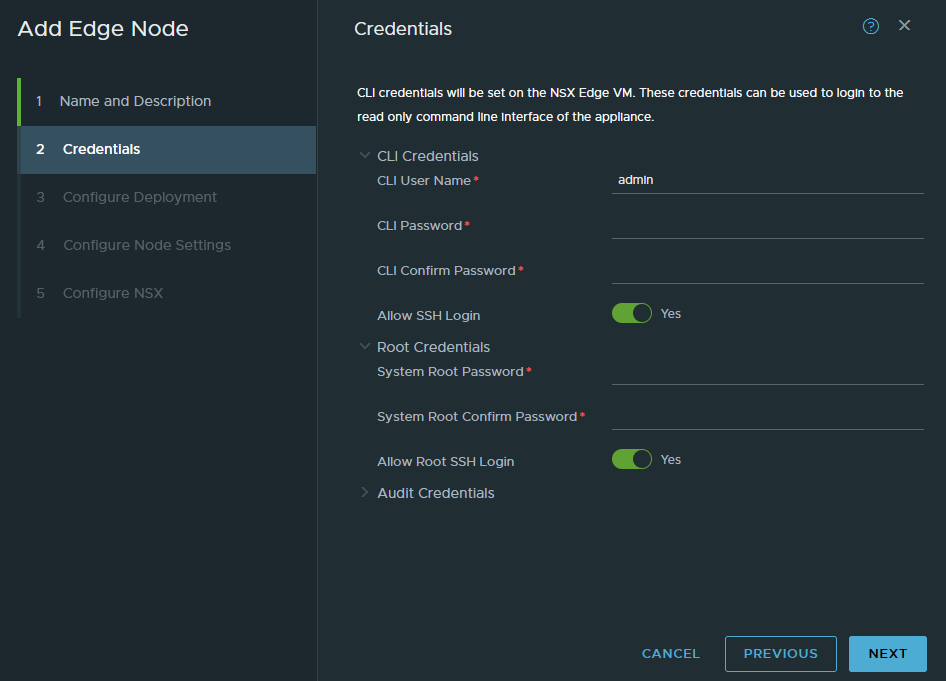
Add a new Edge node. FQDN’s are required, set the form factor to small which is fine for our purpose but we cannot use NSX-T’s load balancer with a small form factor. Set the reservations to 0 because we don’t want to waste any resources.
Enter a password for the root and admin user. Don’t bother with the audit user. Enable the SSH service if needed.
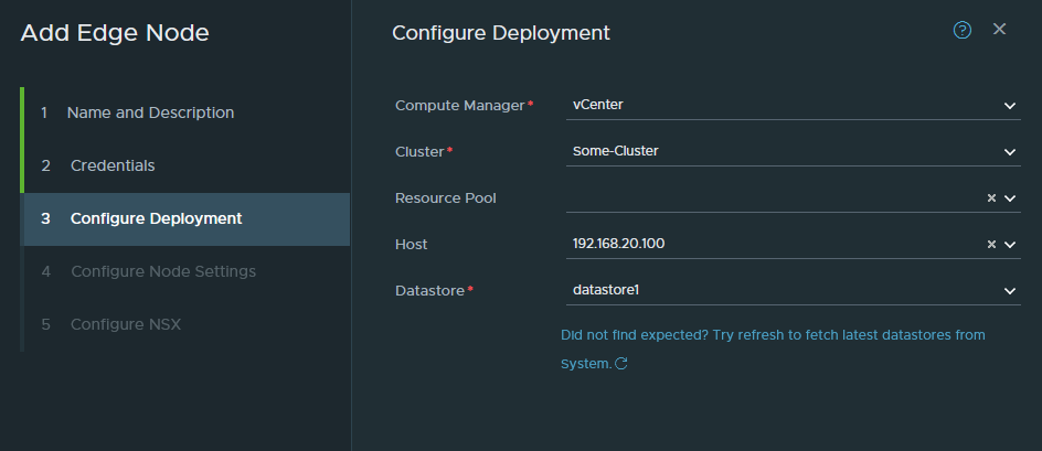
Select the cluster, host and datastore to install the Edge VM.
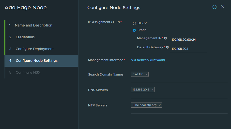
This is the part we configure the management interface of the Edge node. It has to have an untagged interface and in our case it’s just VM Network (untagged VLAN 20). You cannot use a trunk-link or tagged interface for the management interface.
Configure the IP address (192.168.20.60/24) and the DNS settings.
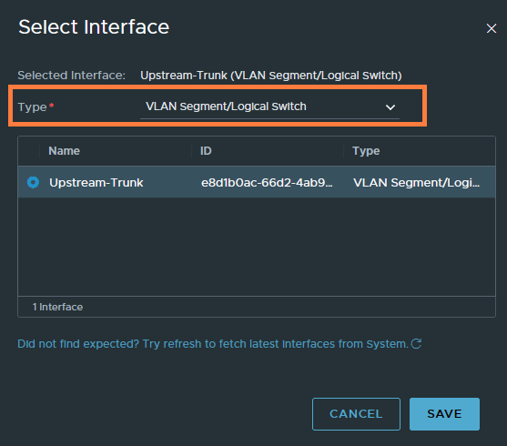
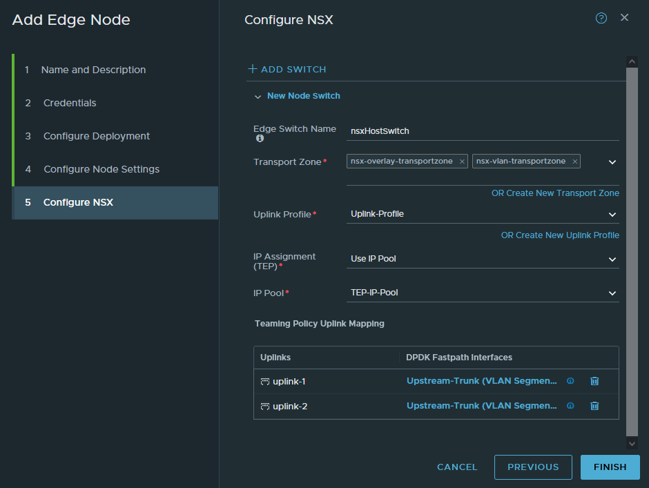
Add both the overlay and VLAN transport zone. Both zones are mandatory. Select the uplink profile and the IP pool we created. Lastly, select the ‘Upstream-Trunk’ port group (VLAN 0-4094) as the uplink interfaces. It’s under the “type VLAN Segment/Logical Switch”.
Finish and repeat the same process for the 2nd Edge Transport Node. Obviously, don’t use the same FQDN (step 1) and management IP address (step 4). It should be edge02.nsxt.lab and 192.168.20.61/24. Refer back to the topology if needed.
The deployment takes a while and should be successful as shown below.

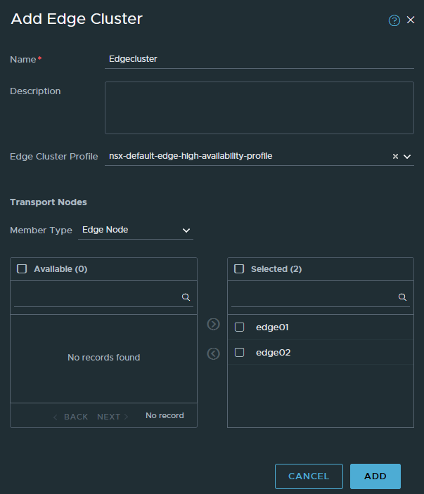
The next step is to add both Edge nodes in a cluster.
System > Fabric > Nodes > Edge Clusters
Add a new cluster and add both edge01 and edge02 to it.
Creating the Tier 1 gateway and overlay segments
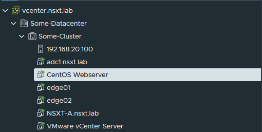
For demonstration purposes, I’ll be using a CentOS VM. So make sure to have something similar available.
Let’s create a Tier 1 gateway. This will be a distributed router, primarily used for intra-VM connectivity. It’s not used for external connectivity such as the internet. Any ESXI host that you’ll add to the same overlay transport zone and is part of the same cluster, will have this router as well with the exact same IP and MAC addresses. Edges are technically transport nodes as well, so they will also have this router.
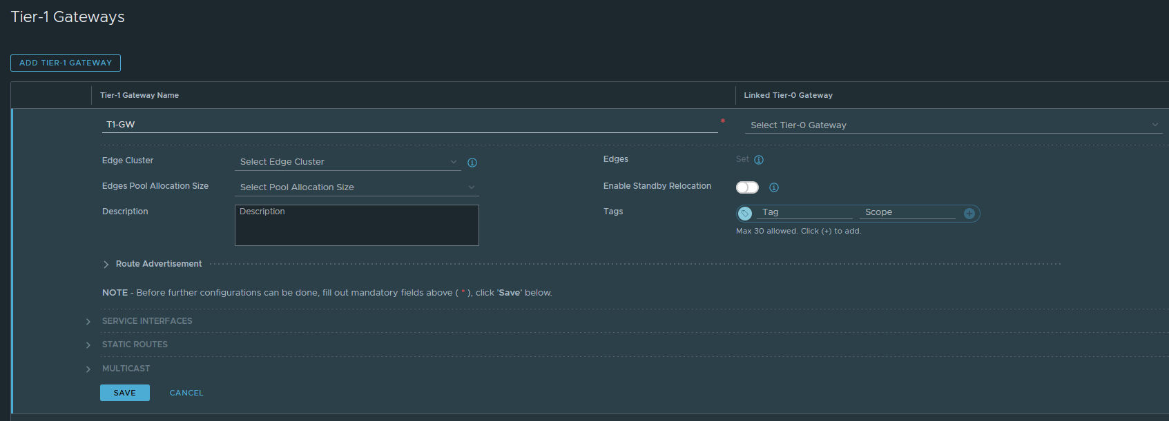
Networking > Connectivity > Tier-1 Gateways
Give it an appropriate name and you do not need to configure anything else at this point. We cannot select a Tier-0 Gateway yet because we still have to create it. Click save if you’re done.
Now we’ll get to the illustration aspect of this series. You may have been wondering how we connect a virtual machine with NSX-T? That’s what segments are for. Once you create them, they’ll show up as a port group in vCenter and you can use them as the network adapter for a virtual machine. So let’s create one.
Networking > Connectivity > Segments
Add a new segment, name it ‘Web-Seg’. Select the Tier-1 gateway and the ‘nsx-overlay-transportzone‘ as the Transport Zone. This will be an overlay-backed segment, not to be confused with a VLAN-backed segment. And under subnets (IPv4), this is just essentially a default-gateway address just like what your router would have. I’ve gone with 172.16.10.1/24. Click save if you’re done.

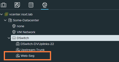
We can now see the port group added in vCenter under our dSwitch. It has an ‘N’ to its icon, which identifies that it was created by NSX-T.
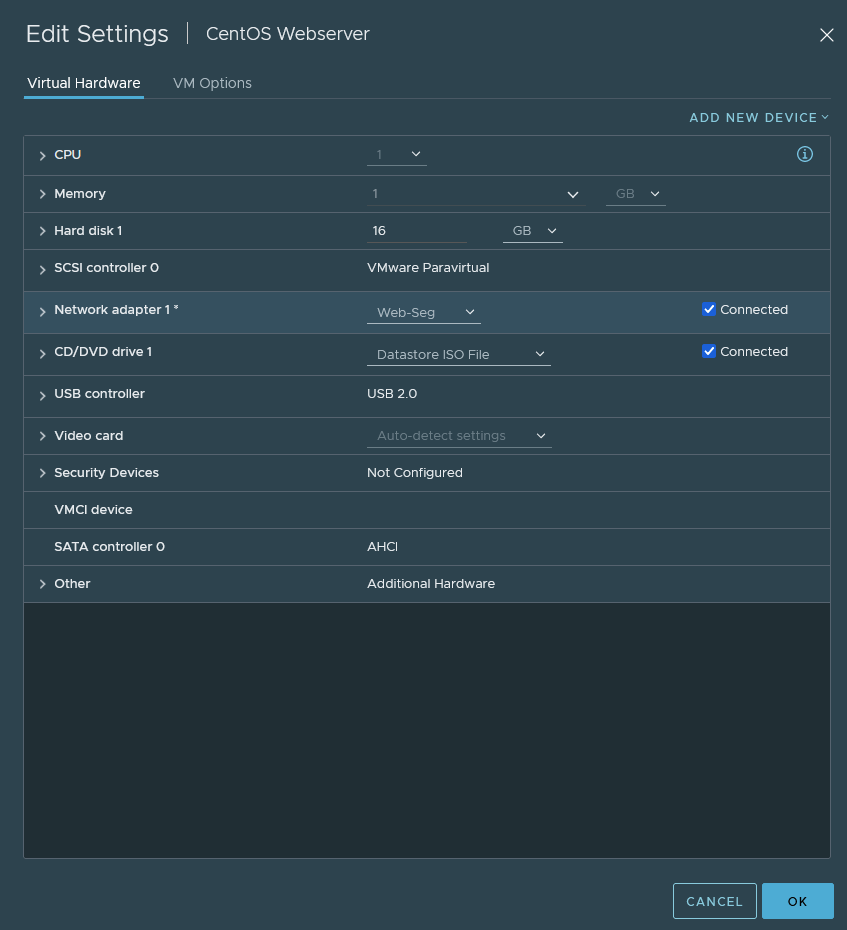
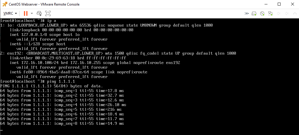
If we get our CentOS VM out, assign it with the Web-Seg port group then we should be able to ping its default gateway (172.16.10.1/24) and every other VM in the 172.16.10.0/24 subnet.
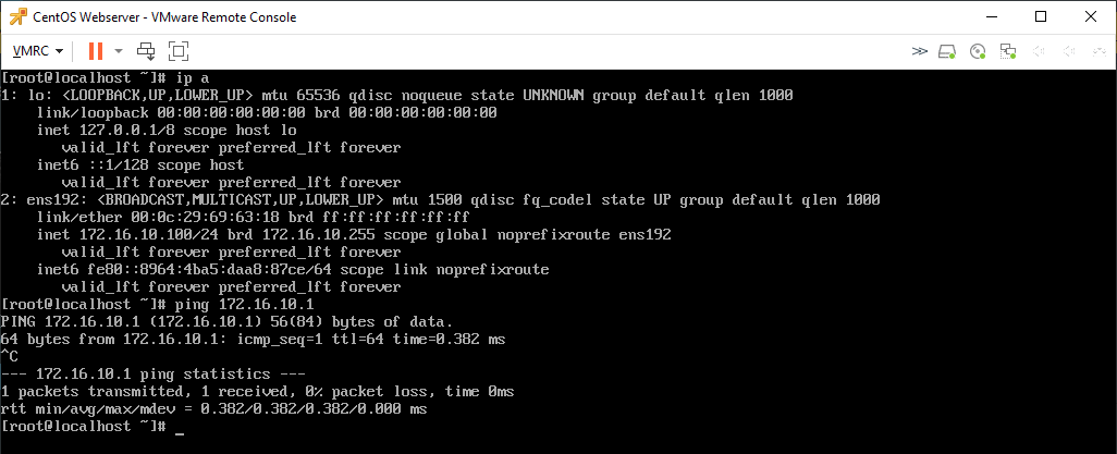
I configured the VM with the address of 172.16.10.100/24 and it does ping the default gateway successfully (172.16.10.1/24). However, there’s no internet access because the T1 gateway is not connected to the T0 gateway which is not configured yet.
Tier-0 gateway and connectivity with upstream router
We’ll be configuring a tier-0 gateway and setting it up so that it can communicate with our pfSense router. This will be the gateway for external connectivity, and not intra-VM communications. If a VM wants to reach the internet, then this is the gateway that will be used. Before we begin with creating a Tier-0 gateway, we have to create a VLAN-backed segment.
The VLAN-backed segment will be used for Edge-node uplink interfaces to communicate with the physical upstream router for connectivity (e.g. internet) and routing purposes (static, OSPF and BGP).
Networking > Connectivity > Segments
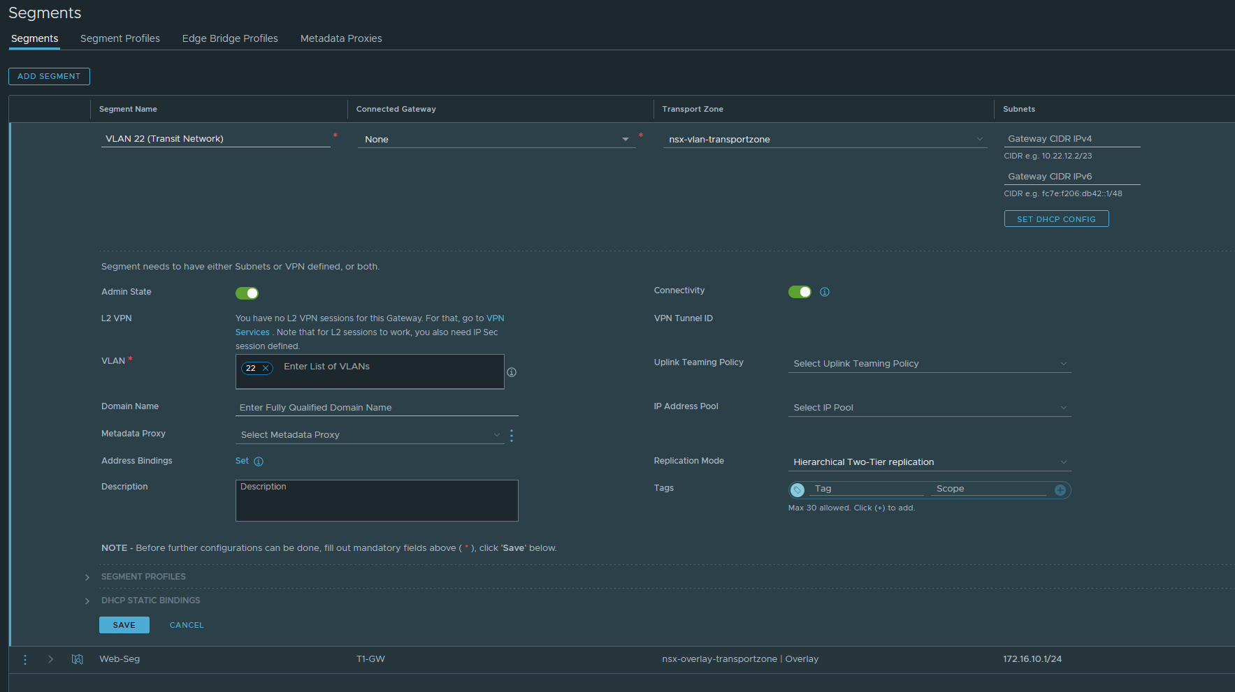
Name it ‘VLAN 22 (Transit Network)’. Do NOT connect it to any gateway and select the VLAN transport zone because this is a VLAN-backed segment. Enter the VLAN 22 ID. Do NOT configure any IP addresses. Click save if you’re done.
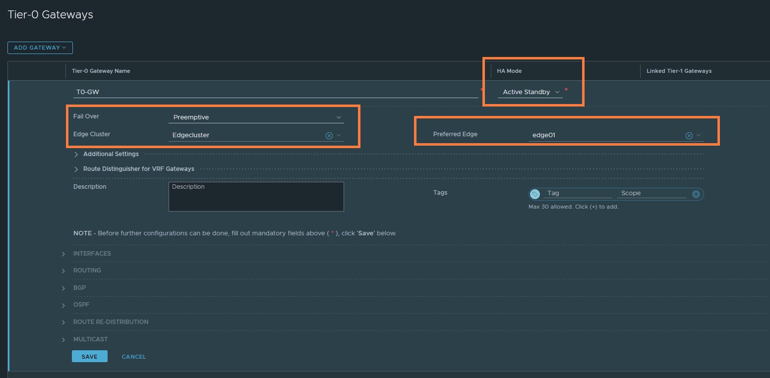
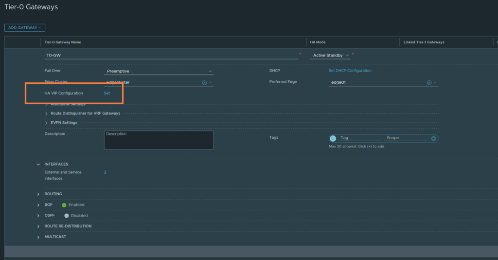
Networking > Connectivity > Tier-0 Gateways
Name it ‘T0-GW’. Set the HA mode to Active Standby. Select the edgecluster and the preferred node if you’ve selected preemptive as the fail over mechanism. Click save if you’re done.
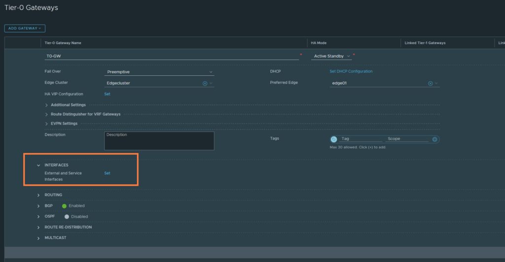
Next, we’ll create some uplink interfaces to communicate with the Transit Network (VLAN 22). We’ll need two interfaces in total and that’s because we have two Edge-nodes in a cluster.
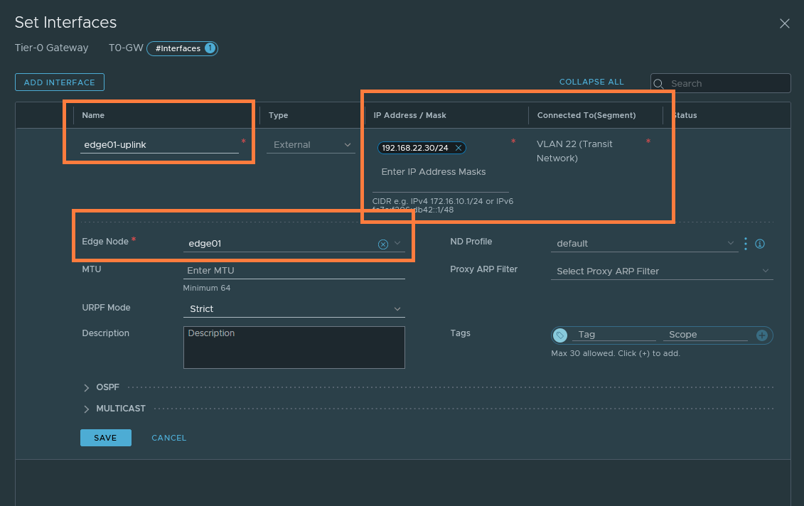
Create the first uplink-interface and name it ‘edge01-uplink’. Set the IP address to 192.168.22.60/24 and this address needs to be within the 192.168.22.0/24 subnet. Select the VLAN 22 (Transit Network) VLAN backed-segment we created earlier. Select edge01 and this interface will be assigned to edge01 at this point.
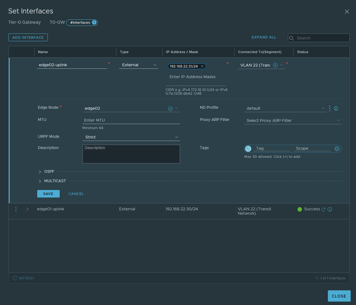
Create a new interface and this time it’ll be for edge02 node. The IP address has to be different from the first interface.
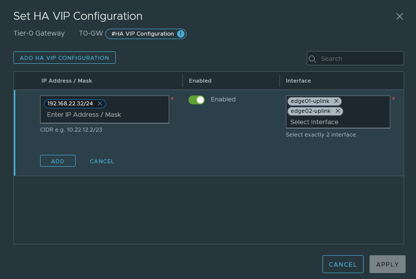
Because we are dealing with two interfaces and two different addresses, static routing can get messy. We do have the option to create an HA VIP address between the two interfaces, so that we work with a single IP which we can use as our next-hop when defining routes.
Set the HA VIP address to 192.168.20.32/24. Select both interfaces; edge01-uplink (192.168.22.30/24) & edge02-uplink (192.168.22.31/24).
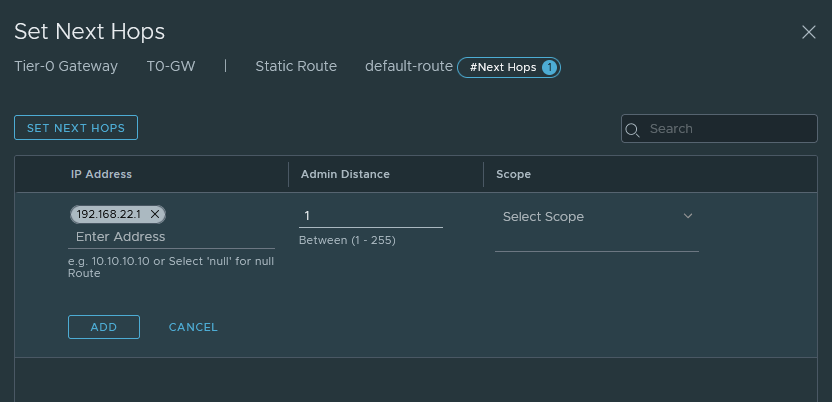
Next, we have to add a default-route for internet access.
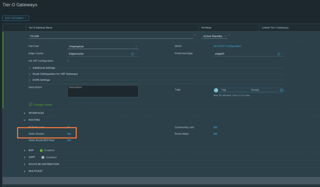
Just name it ‘default-route’ and the destination network should be 0.0.0.0/0.
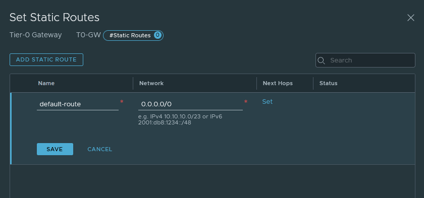
Don’t forget to set the next-hop address 192.168.22.1 which is the interface address of VLAN 22 on the pfSense router.
Attaching Tier-1 gateway with the Tier-0 gateway
Let’s start linking the gateways.
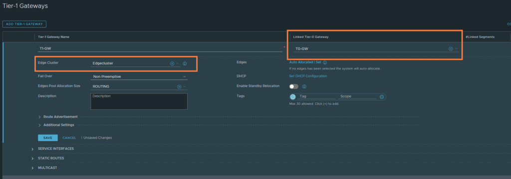
Networking > Connectivity > Tier-1 Gateways
Just select the Tier-0 gateway and select the Edgecluster. Then hit save.
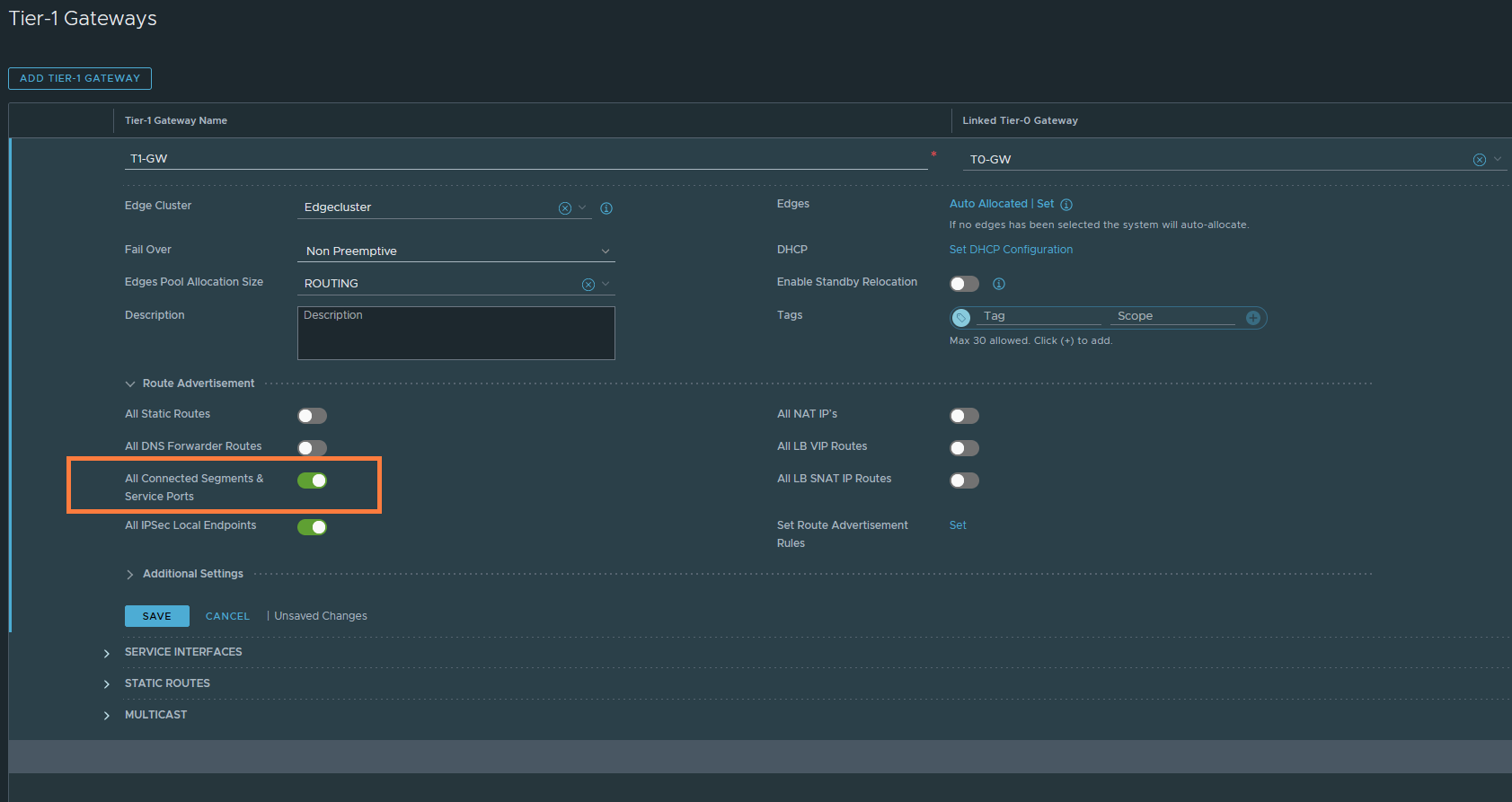
We want the Tier-1 gateway to advertise its own routes to the Tier-0 gateway. The T1 routes are basically segments that you’ve attached to the T1-GW, such as ‘Web-Seg’ 172.16.10.0/24. This does not advertise it to the physical upstream router, obviously.
Under ‘Route Advertisement’ enable ‘All Connected Segments & Service Ports’. Then hit save.
We have to create a return route on the upstream router to be aware of 172.16.10.0/24 (Web-Seg).
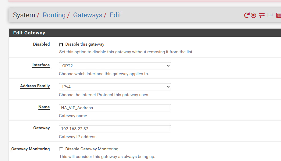
System > Routing > Gateways
Let’s add the next-hop address which will be the HA VIP address of the uplink interfaces of our edges.
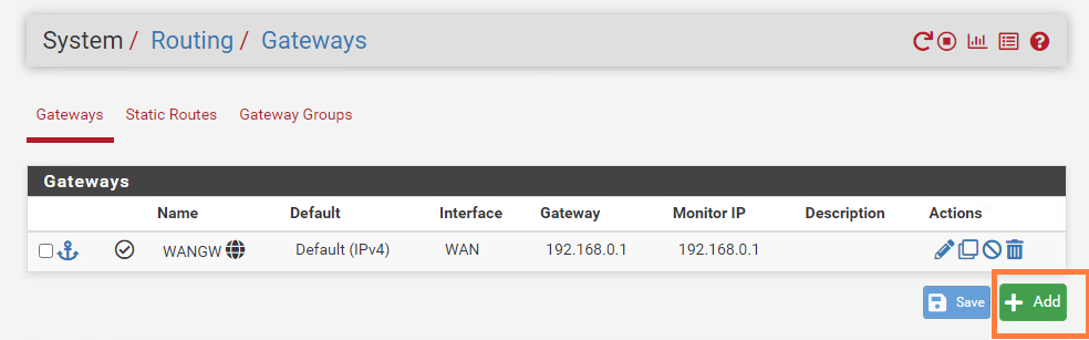
The interface is OPT2 (or just VMX1.22 to be very precise). The next-hop address is the HA VIP address of the uplink interfaces of our edge nodes – which just is 192.186.22.32. Then hit save.
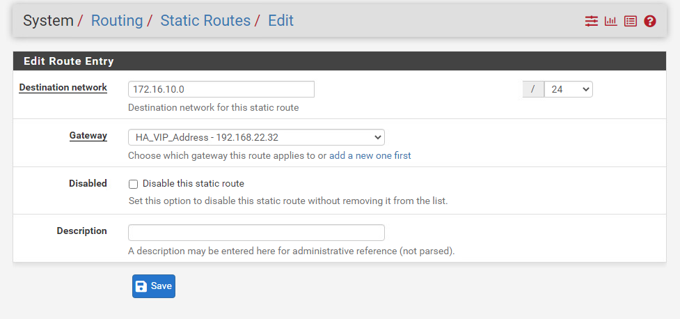
Now we do have add a destination network (172.16.10.0/24) and use the HA_VIP_Address as the next-hop/gateway. pfSense and its naming schemes can be confusing, I am not sure why the terminology default-gateway is used instead of next-hop when we’re doing static routing.
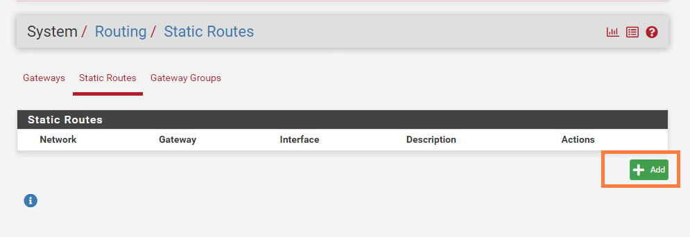
System > Routing > Static Routes
We should be able to reach the internet now with our CentOS VM. The VM is still part of ‘Web-Seg’ which is an overlay segment and has a subnet of 172.16.10.0/24.
Overlay vs VLAN segments
The difference between the two might be confusing. But overlay segments are part of overlay transport zones. In fact they are connected to Tier-0 or Tier-1 gateways. Overlay segments take advantage of VXLAN/GENEVE protocol and in NSX-T, it’s GENEVE. The protocols can transmit layer 2 packets over layer 3 – which essentially means that you can span L2 over L3 such as the internet.
VLAN segments are part of the VLAN transport zone. They are mainly used for north-south traffic between the edge and the physical infrastructure (router, switches etc.). VLAN segments can also be used for VM’s which would ignore NSX-T’s routing (e.g. T0/T1 gateways) and provide direct connectivity to the physical router. It does require the ESXI host (Transport-Node) to be assigned in a VLAN transport zone. We have already done that when we set up our transport-node profile for our cluster.
If you are wondering; why would you create a VLAN backed segment instead of just using VDS port groups? Because VLAN segments are part of the VLAN transport zone and you can utilize the NSX firewall for VLAN segments which you can’t do for standard VDS port groups.
Another difference is that VXLAN/GENEVE can go up to roughly 16M segments while VLAN’s are limited to about ~4094.
Hello, this is exactly what I was looking for in a step-by-step.
I ran into a problem when creating the edge nodes, it doesn’t see the Upstream-trunk segment that I created earlier. I refreshed a couple of times, and waited a few minutes, but the field is just empty. I do see it and in a green success state if I look at the segments section. Any suggestions?
There’s an option field to select VDS port groups or VLAN segments. You’re not seeing the Upstream-trunk segment because it’s not a VDS port group, it’s a VLAN segment.
Nevermind, found that the TZ was using the default rather than the one that I created.
hi I followed your guide , but i cant get the edge node to come online, its in a pending state and i see the error
PNIC/Bond list failed: no msgClient for host.
and when editing the edge node i see that the uplink name is replaced with a guid, so i am assuming it cant see my uplink.
not sure what or where to check
oh my gawd! thank you for such a great guide
The edge config, the static routing on the t1, the physical router, the plain common sense definitions.
Currently, in my lab there is East-West and North-South traffic!
Wow, after almost 2 weeks being stuck, the paved the path forward! Thank you!!!
I’m glad it helped you out!
does the web-segment and VLAN22(Tansist Network) segment need to connect to the Tier 1 Gateway ?
Overlay segments such as the “web-segment” do have to connect to T1 gateways. That’s the purpose. But VLAN-based segments such as VLAN 22 (Transit Network), they do NOT connect to gateways.
Great guide!! I was stuck for more than 2 weeks building a lab NSX-T 4 . Tep tunnel always down when Edge and Transport node in same VLAN , this saved me.
I cant express my gratitude. Thanks a ton!!