Usually the phase 2 subnets are different with site-to-site IPSEC tunnels. When the subnets are the same on both ends, 1:1 NAT should be used and this a very complicated process.
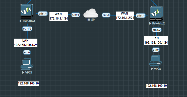
As we can see we have two local networks with the same subnet and the idea here is that we translate each one of them to a different subnet.
Site 1:
Local Network: 192.168.100.0/24 -> translated to 10.0.1.0/24
Remote Network: 10.0.2.0/24
Site 2:
Local Network: 192.168.100.0/24 -> translated to 10.0.2.0/24
Remote Network: 10.0.1.0/24
Interfaces overview
Site 1:
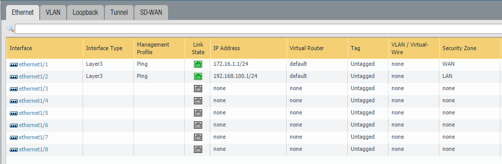
Site 2:

Then we have our tunnel interfaces where we attached the IPSEC security zone. There’s no need to assign an address to this tunnel interface unless we are using a dynamic routing protocol such as OSPF. And we aren’t using OSPF here.
Site 1:
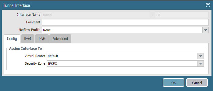
Site 2:

IKE Gateway and IPSEC tunnel
Nothing was specified under the tab “Advanced Options”.
Site 1:
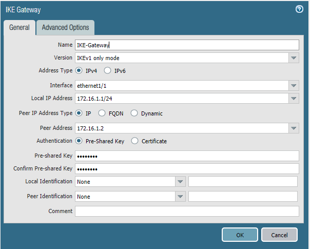
Site 2:

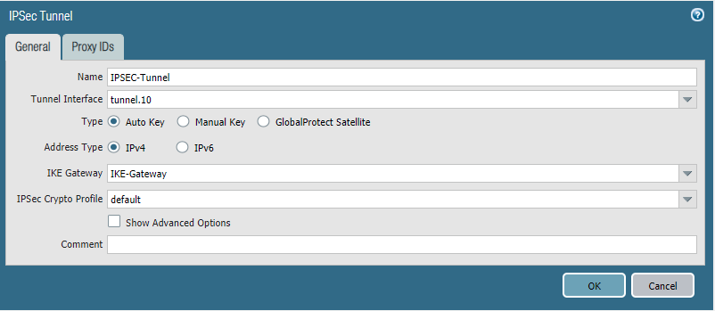
And our IPSEC tunnel. No Proxy ID’s were defined because they’re not required.
Site 1:

Site 2:
Security policies
On the external interface we’ll have to allow ipsec and ike for the 1st phase. The application ping is sufficient for testing purposes. Both rules are bidirectional meaning that either side can initiate the connection and be the receiving end.
Site 1:
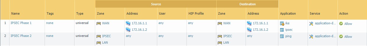
Site 2:

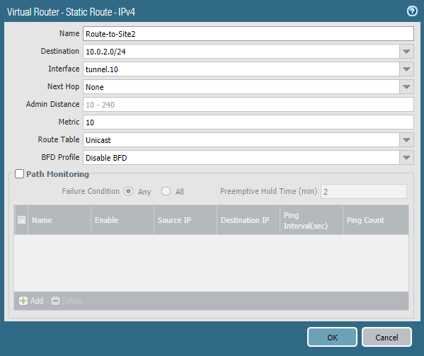
Routes
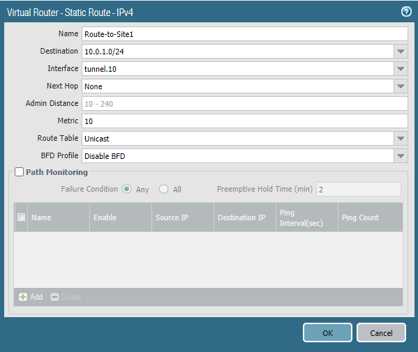
Site 1:
The local network on site 1 is 10.0.1.0/24 (translated from 192.168.100.0/24) and the remote network is 10.0.2.0/24. We’ll use the tunnel interface here. No next hop is required.
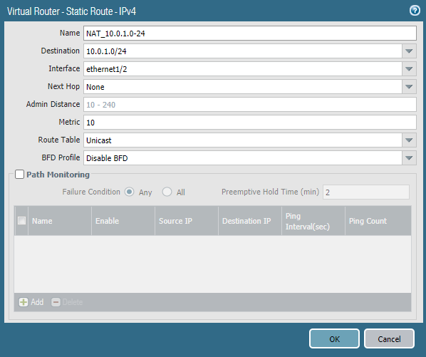
A route to 10.0.1.0/24 has to be added and the egress interface should be a local interface which is ethernet1/2 (LAN). No next hop is required.
Site 2:
The local network on site 2 is 10.0.2.0/24 (translated from 192.168.100.0/24) and the remote network is 10.0.1.0/24. We’ll use the tunnel interface here. No next hop is required.
A route to 10.0.2.0/24 has to be added and the egress interface should be a local interface which is ethernet1/2 (LAN). No next hop is required.

NAT policies
Basically how this works is by translating an address with a 1:1 correlation, meaning that 192.168.100.10 will be either 10.0.1.10 or 10.0.2.10.
Client site 1: 192.168.100.10 -> translated to 10.0.1.10 (and the address client 2 will see)
Client site 2: 192.168.100.10 -> translated to 10.0.2.10 (and the address client 1 will see)
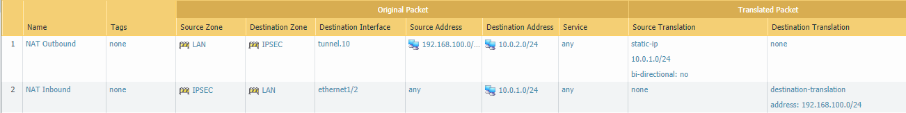
Site 1:
192.168.100.0/24 will be source-translated to 10.0.1.0/24. The source zone will be LAN and the destination zone has to be the IPSEC zone because that’s where 10.0.2.0/24 is being forwarded to from site 1.
And a destination NAT policy is also required. The source zone is IPSEC and the destination zone is LAN which will be 10.0.1.0/24 and this will be translated to 192.168.100.0/24.
Make sure to select ‘Static IP’ as the type for either source/destination translations.
Site 2:
192.168.100.0/24 will be source-translated to 10.0.2.0/24. The source zone will be LAN and the destination zone has to be the IPSEC zone because that’s where 10.0.1.0/24 is being forwarded to from site 2.
And a destination NAT policy is also required. The source zone is IPSEC and the destination zone is LAN which will be 10.0.2.0/24 and this will be translated to 192.168.100.0/24.
Make sure to select ‘Static IP’ as the type for either source/destination translations.

Can we use bi directional nat enabled on first nat rule . That will be sufficient or not? So, second NAT (DNAT) policy not required right?