Firewalls configured in an Active/Active High-Availability differs vastly from Active/Passive configurations because they’re much harder to configure and manage. Active/Active handles environments with random or unpredictable routes better like when there’s a load balancer in front of the HA pair.
In an Active-Active Cluster, both firewalls are running simultaneously with load-balancing algorithms between the devices. Both devices should be configured almost the same, most settings will carry over to the secondary device. But settings such as ‘Management Interface’ settings (Device > Setup) won’t synchronize to the peer and thus the management interface should be configured individually per device. See the documentation for which settings don’t synchronize.
Interface types
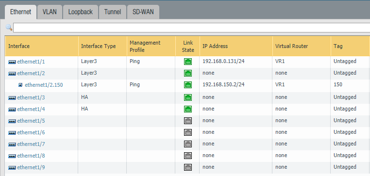
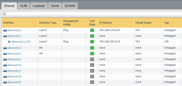
- In HA Active/Active mode, IPv4/IPv6 configuration of physical interfaces (Network > Interfaces) are bound to the device itself. They do not carry over. Each member of the pair will have its own IP-address. Settings such as the management profile or the security zone for that interface does synchronize with the peer. Or when adding a sub-interface.
- Floating IP addresses are virtual addresses that are only active at one firewall at a time. When the primary fails then it’ll “float” to the secondary device. They are preferred for internet facing interfaces.
- ARP-Load-Sharing addresses are also virtual addresses but they’re active on both firewalls at the same time with load balancing algorithms. Usually preferred on the internal side of the network. Keep in mind that this form of a virtual address can cause a few issues. Floating addresses tend to be more reliable.
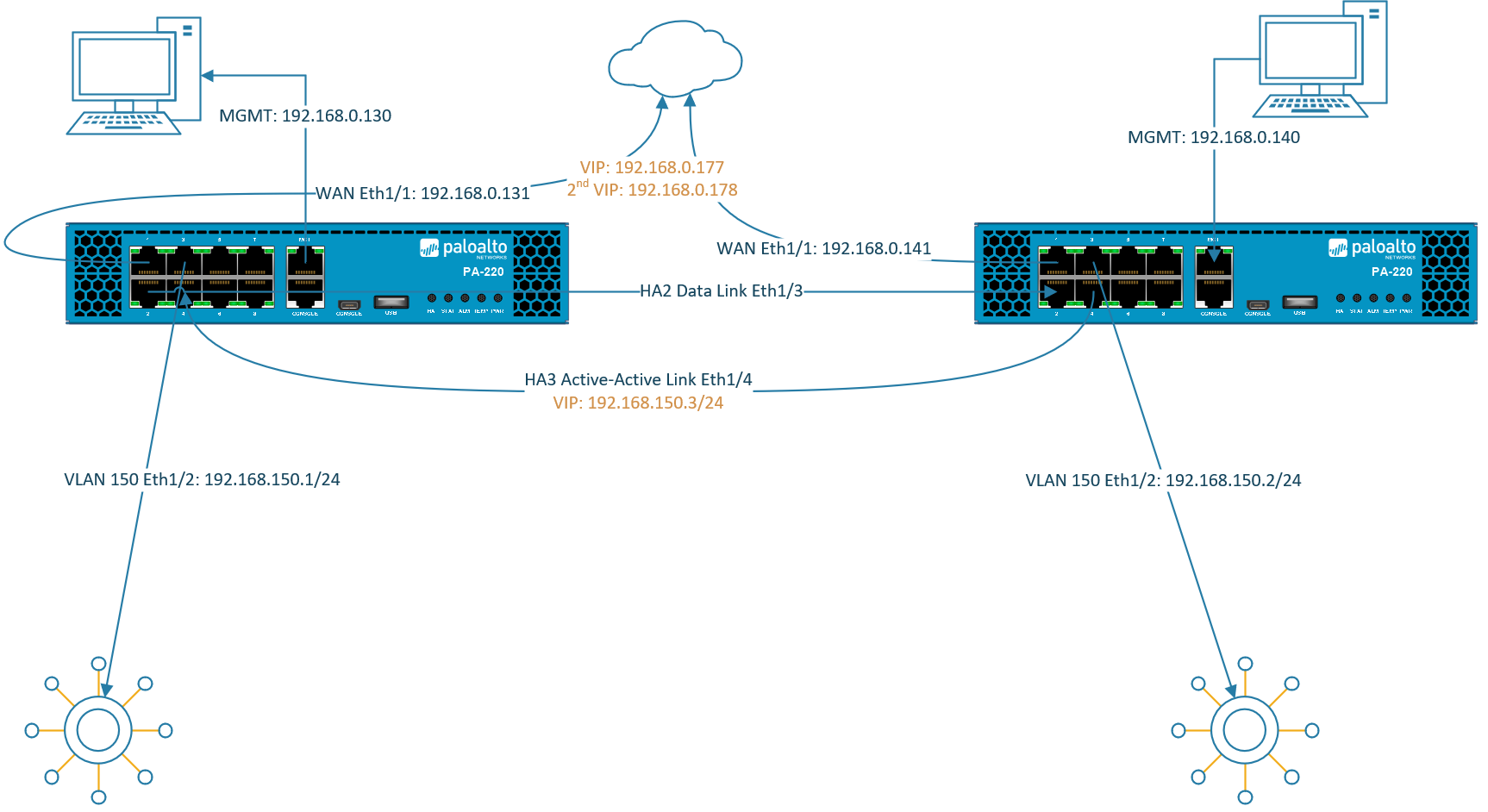
Clients are supposed to use the virtual addresses as their default gateway for fail-over/load-balancing reasons.
HA interface types
- HA1 also known as the “Control Link” basically synchronizes configurations between the devices. Usually the management interface is used for this HA interface although a dataplane interface would work as well. It has to be a Layer 3 interface and it doesn’t have to be in the same L2 domain.
- HA2 also known as the “Data Link” is used to synchronize sessions, ARP and forwarding tables. It can operate at Layer 2 so that it doesn’t need to be configured with an IP address. If both devices aren’t in the same L2 domain, then the HA2 interface should be configured with an IP address.
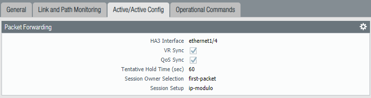
- HA3 is the Active/Active link dedicated just for Active/Active mode. This link will have the configurations for the virtual addresses and the load balancing algorithms. Here we will also find algorithms for session owner selection and setup.
Prerequisites
This guide won’t explain how to set up a Palo Alto firewall so I won’t be going through every single installation process and I expect you to be intermediate at networking.
- Two Palo Alto firewalls
- Same model
- Same PAN-OS version
- Identical VM port groups (vSwitches or dSwitches)
Virtual Machine Interfaces
In my case the VM Network port group is the management and the HA1 interface.
Primary FW #1

Secondary FW #2

Interfaces on the firewalls
Primary Firewall #1
Configure the following interfaces “Ethernet1/3” and “Ethernet1/4” as an “HA” type of an interface.
Secondary Firewall #2
Configure the following interfaces “Ethernet1/3” and “Ethernet1/4” as an “HA” type of an interface.
Device > High-Availability > General
Primary Firewall #1
Make sure to configure the “Peer IP address” correctly. The address should be the Management IP address of the secondary firewall. Group ID can be set to 1 since this will be the first HA pair. Device ID should be 0 which will indicate that this firewall is the primary.

Change the Device priority to 90 and select Preemptive. The HA-timer can be changed to a more aggressive setting, but recommended should be enough.

The default interface should be the Management Interface for the HA1 Control Link.

Select Interface “Ethernet 1/3” as the HA2 Data Link interface. Because it’s a Layer 2 interface there’s no need to configure IP addresses. Select ‘Split Datapath’ as the option for HA2 Keep-alive.

Secondary Firewall #2
Set the Primary firewall’s Management IP address as the peer. Group ID should be identical as the peer, so it’s 1. Device ID should be set to 1 which makes this the secondary device.

Select Pre-emptive and leave the device priority at default (100).

Make sure the Management Interface is the HA1 Link.

Select the interface “Ethernet 1/3” as the HA2 Data-Link interface. Check the box for “split-datapath” under HA2 Keep-alive.

Device > High Availability > Active/Active Config
Now we’re getting to the actual Active/Active configuration where we’ll configure Floating IP & ARP Load balancing addresses in a moment. On the primary firewall select “Ethernet 1/4” as the HA3 Active/Active interface. Select “First Packet & IP Modulo” and check “VR Sync & QoS Sync”.
You don’t have to repeat the same process on the other firewall because it should be synchronized.
On the External side (Ethernet 1/1) I’ve added two floating IP addresses. Floating IP addresses are glued to the given device until that device fails and it’ll move over to the functional device, hence the terminology “floating”. For example; clients won’t be able to use the second firewall if their default gateway is configured with a floating IP address. As a result that particular firewall will be heavily loaded while the second is barely being a part of the scene. This is where ARP-load-sharing comes into play.
ARP-load-sharing uses algorithms to determine (such as IP Modulo/IP Hash) the firewall that should respond to the client. ARP-load-sharing IP addresses should never be used on the external side and only in between the firewall and the endpoints. IKE, Global Protect Gateways, Global Protect Satellites and NAT Policies only work with floating IP addresses.

Device > High-Availability > Link and Path Monitoring
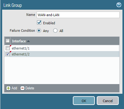
Defining the fail-over policy has to be configured individually at each device because it’s one of the settings that does not synchronize. Link Group only monitors the physical aspect like interfaces and cables. It can’t detect if there’s internet access or not.
Ethernet 1/1 (WAN) & Ethernet 1/2 (VLAN)
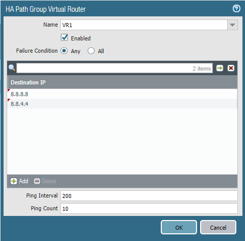
Path Group uses ICMP pings to a given destination to validate if there’s internet access or not. Highly recommended to select the Virtual Router as the object to monitor.
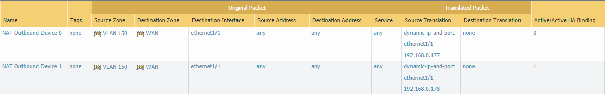
NAT Outbound Policies
Because the Palo Alto doesn’t allow both devices to share the same floating IP address with PAT policies, each device should be configured to use their own floating IP address, under the Active/Active HA Binding tab.
Testing
To verify everything is working, a client should be configured using the ARP-Load-Sharing IP address (192.168.150.3) as default gateway and a simple ping to google should do. If this fails, set the default gateway corresponding to a device’s physical interface (192.168.150.1 & 192.168.150.2) to pinpoint which device is causing the issue.
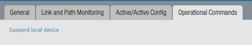
After everything is working as intended, it’s a good idea to shut one of the firewalls down to see if the fail-over works. Instead of manually shutting down the firewall, there’s an option under Device > High Availability > Operational commands > Suspend Local Device.
To enable it again.

Very well written tutorial. Easy to follow yet goes extremely in depth at the same time.